Step 3 - connect data acquisition signal lines – Measurement Computing 652u Quick Start User Manual
Page 2
Printed in Hungary
IOtech
25971 Cannon Road
Cleveland, OH 44146-1833
Phone: (440) 439-4091
Fax: (440) 439-4093
Intern
LED Notes:
The “Power” LED blinks during device detection and initialization; then remains on solid as long as
the module has power. If there is insufficient power the LED will go off. Th
e “Active” LED is on whenever active
communication is taking place between 652u and the host PC. It will be on solid during data acquisitions.
Step 3 - Connect Data Acquisition Signal Lines
CAUTION
Turn off power to the system devices and externally connected equipment before
connecting cables. Electric shock or damage to equipment can result even under
low-voltage conditions.
Take ESD precautions (packaging, proper handling, grounded wrist strap, etc.)
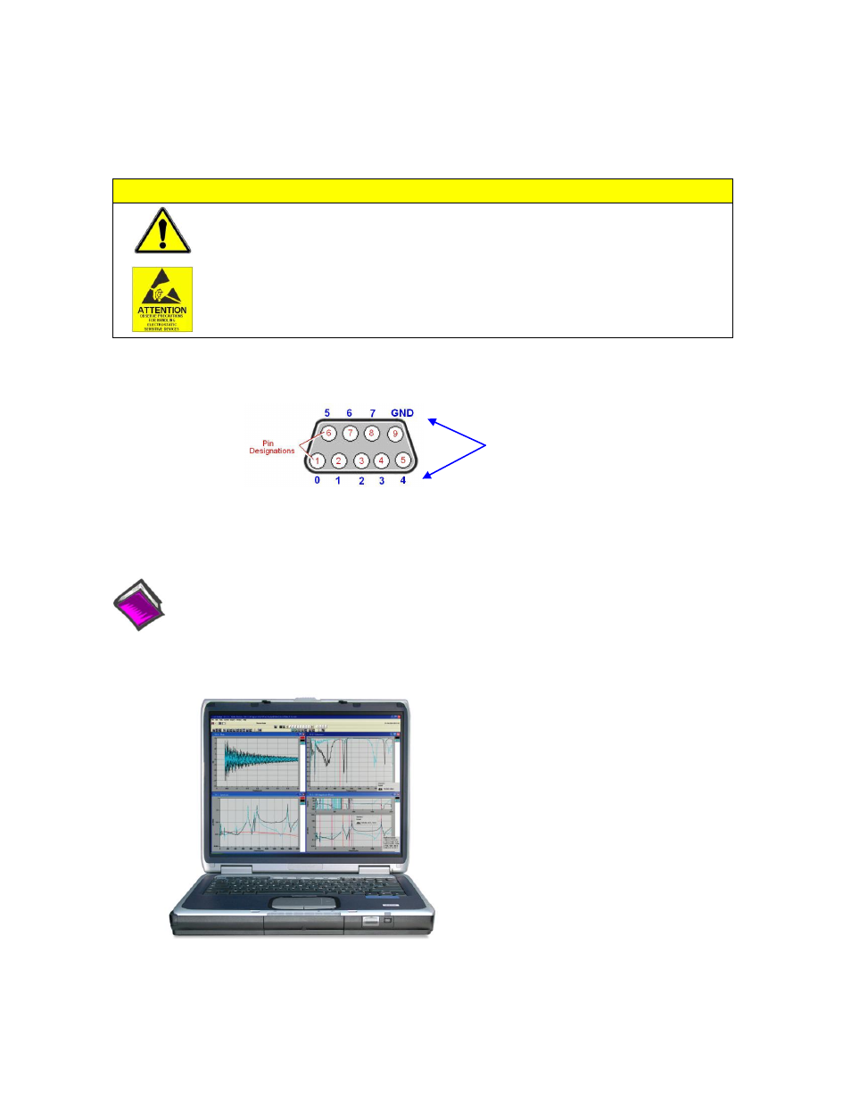
The 652u has 10 analog channel inputs (CH1 through CH10) via front panel BNC connectors and 8 digital I/O
lines via rear panel DB9 connector.
Prior to making signal connections review the Specifications chapter of your user’s manual to ensure that the input
signals do not exceed the specified limits. The manual is included in PDF format on the CD.
Reference Notes:
Adobe Acrobat PDF versions of documents pertaining to IOtech 652u are automatically installed onto
your PC’s hard-drive as a part of product support at the time of software installation. The default
location is the Programs group. It can be accessed via the Windows Desktop Start Menu.
*324996A-01*
324996A-01
Digital I/O
Channel
Designation