Step 3 – connect signal inputs – Measurement Computing Personal Daq/50 Series User Manual
Page 2
*324352C-01*
324352C-01
Measurement Computing, 10 Commerce Way, Norton, MA 02766
phone: (508) 946-5100;
email: [email protected]
Printed in Hungary
Step 3 – Connect Signal Inputs
CAUTION!
Never touch connector pins or circuit components unless you are following ESD guidelines in an
appropriate ESD controlled area. Such guidelines include the use of properly grounded mats and wrist straps,
ESD bags and cartons, and related procedures.
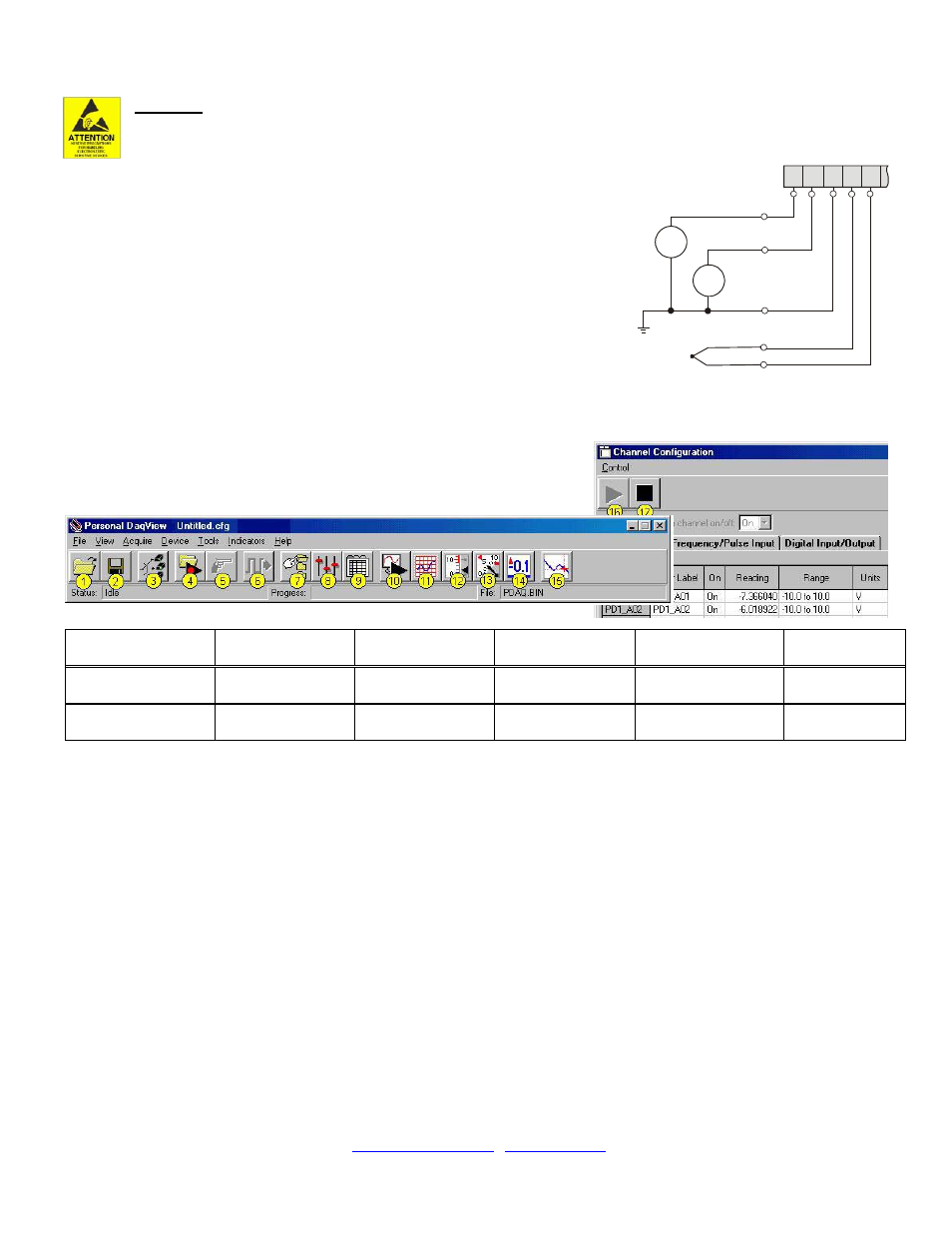
Use Personal Daq’s screw terminals to connect channel inputs. The terminal blocks are
detachable for ease in making connections. Device labels identify input types and channel
numbers. Each Analog Input channel can be configured for single-ended or differential
volts, or for differential thermocouple inputs. The non-analog channels are designated as
Frequency/Pulse Input (F) and Digital I/O (D).
For Personal Daq, thermocouples are to be connected in differential mode only. This is
because single-ended connections can result in noise and false readings. In regard to
Differential connection, the red wire connects to the channel’s Low (L) connector; and
the second color-coded wire connects to the channel’s High (H) connector. The user’s
manual contains additional information.
Step 4 – Start Personal DaqView & Configure the System
From Windows, open Personal DaqView by double clicking on its icon, or use the
Desktop Start menu to access the program. You will find Personal DaqView
listed in the desktop’s Program group. The software will identify your Personal
Daq device and bring up the Main Control Window. This window is detailed in
the Personal Daq User’s Manual included on the installation CD.
Button Reference:
(1) Open
Configuration File
(2) Save
Configuration File
(3) Select
Active Device
(4) Arm Trigger
for Disk Recording
(5) Manual Trigger
(6) Update
Digital Outputs
(7) Configure
Data Destination
(8) Configure
Acquisition
(9) Configure
Channel Settings
(10) Update
All Indicators
(11) Scrolling Charts
(12) Bar Meters
(13) Analog Meters
(14) Digital Meters
(15) View Data
(16) Enable Readings
Column
(17) Disable
Readings Column
To configure channels
, first click toolbar button (9). This opens the Channel Configuration Window with the Analog
Input screen selected. You can change from one configuration screen to another via three tabs (Analog Input,
Frequency/Pulse Input, Digital Input/Output).
To configure acquisition parameters
, first click button (8). This opens the Configure Acquisition Window, with the
several parameters you can change, including Pre-Trigger, Trigger, Post Trigger, Averaging, and Scan Rate.
To assign a filename and folder
for saving acquisition data, first click button (7). This opens the Data Destination
window
. From here you can assign a filename and a folder location. Detailed information is provided in
the user’s manual.
To Collect Data
: Click the
This starts the acquisition. The data acquisition begins and the readings column becomes active. However, data is not
recorded to disk. Clicking the
toolbar’s display icon buttons (11, 12, 13, or 14) to see your data in the form of a chart or meter. Note that you can view all
display types, or a combination of them, at the same time.
Note: For detailed information, view the PDF documentation located on CD, at our website, or in the Programs Group
[which resides on your PC, after software installation].
V
V
1
2
V
3
V
3+
V
3-
COM
V1 and V2 are
Single-Ended
Inputs
Personal Daq Terminal Block (Partial)
V3 is a Thermocouple
and is a Differential Input
L
H
C
O
M
H
L
1
1
2
2