Hardware setup, Module connection – Measurement Computing DBK52 User Manual
Page 2
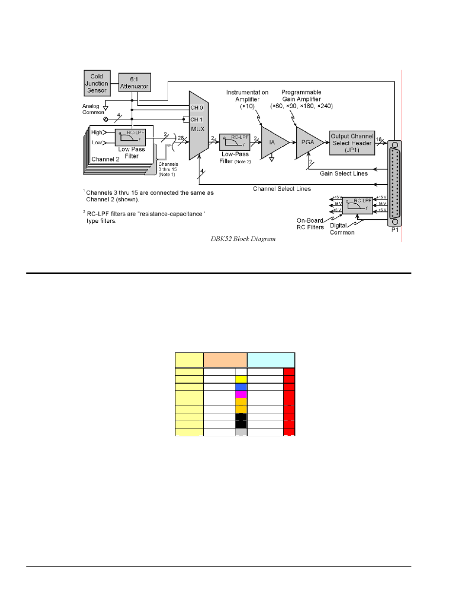
True differential measurements of T/Cs require bias-current referenced to the analog common. Resistors
from each input T/C are connected to the analog common. Filter capacitors across each input operate with
input protection resistors to form a single-pole RC low-pass filter.
Hardware Setup
Module Connection
The DBK52 has miniature T/C jacks to connect different types of thermocouples and an analog-ground
access point. Connections are provided for 14 thermocouples. Thermocouple polarities must be
observed. Thermocouple types J, K, T, E, N28, N14, S, R and B are supported by the LogView or
DaqView software and may be connected to DBK52 board channels CH2 through CH15.
T/C
Type
(+) Lead to
Channel-Hi
(-) Lead to
Channel-Lo
J White
Red
K Yellow
Red
T Blue
Red
E Violet
Red
N28 Orange
Red
N14 Orange
Red
S Black
Red
R Black
Red
B Gray
Red
Note: CH0 is reserved for the cold-junction compensation sensor (factory installed).
CH1 is permanently shorted to allow software-driven auto-zero to compensate for
temperature drift.
Thermocouple wire is standardized and color-coded as shown in the table. T/Cs have a very small output.
Long T/C leads can pickup lots of noise. Use shielding as needed, and average several readings in
software to minimize noise effects.
After all connections are in place, secure wires to captive areas (pre-drilled holes) at the rear edge of the
board. Nylon tie wraps (not included) work well for this purpose.
DBK52, pg. 2
989594
DBK Option Cards and Modules