Measurement Computing DBK34A User Manual
Page 3
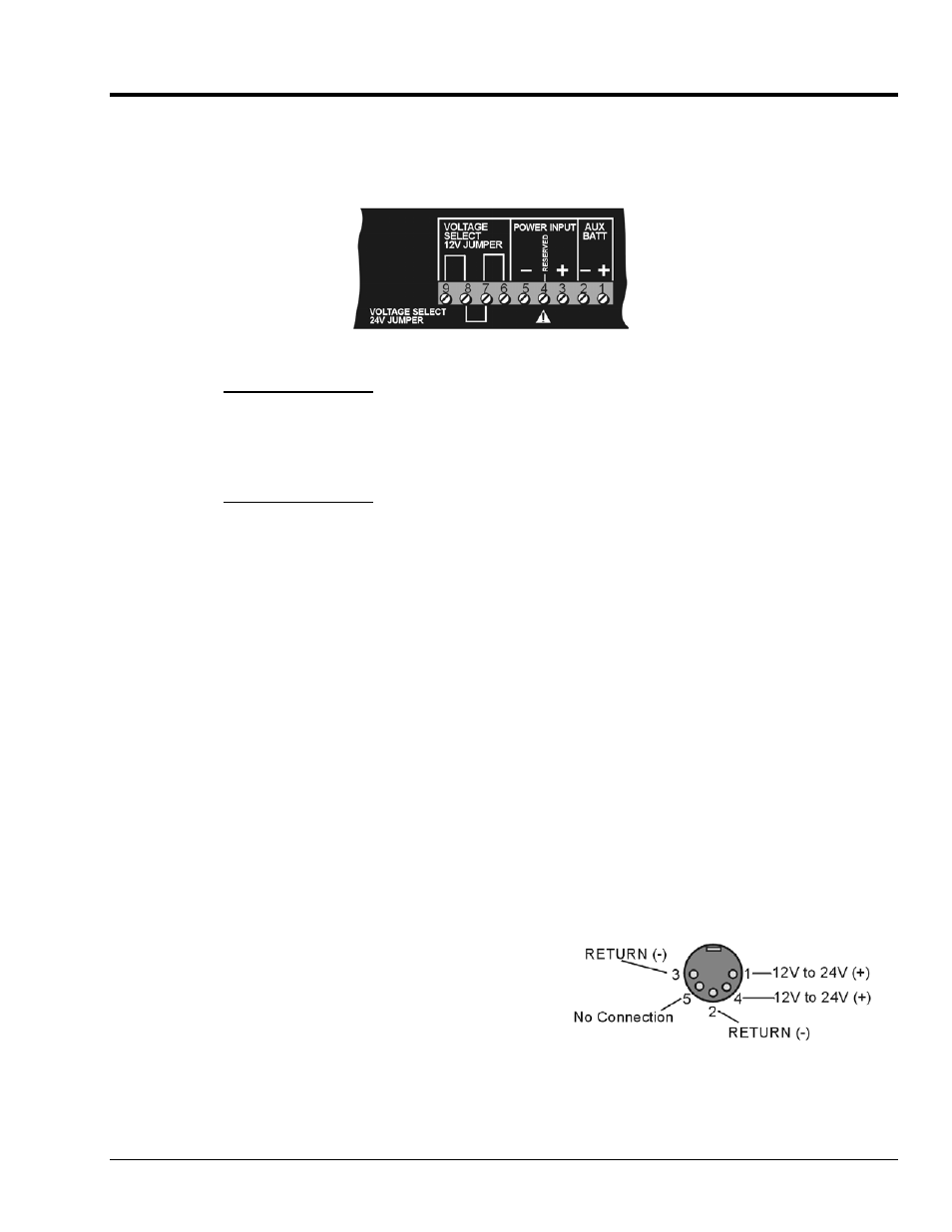
Hardware Setup for 12 Volt (Default) or 24 Volt Operation
The DBK34A is configured for 12 volt or 24 volt operation via placement of jumpers on the front panel’s
screw-terminal block (TB1). DBK34A’s screw-terminal numbers read as follows, when read from left to
right: 9, 8, 7, 6, 5, 4, 3, 2, 1.
DBK34A’s Screw Terminal Board, TB1
For 12 Volt Operation:
1. Remove jumper from terminals 8 and 7, if present.
2. Use a jumper to short terminals 9 and 8.
3. Use a jumper to short terminals 7 and 6.
For 24 Volt Operation:
1. Remove jumpers from terminals 9 and 8, if present.
2. Remove jumpers from terminals 7 and 6, if present.
3. Use a jumper to short terminals 8 and 7.
Power In (12 or 24 VDC only).
1. Connect the MAIN POWER INPUT (+) positive to Terminal 3 of TB1.
2. Connect MAIN POWER INPUT (-) negative to Terminal 5 of TB1.
TB1’s Terminal 4 is reserved for factory use and is not to be connected by the user.
The use of an optional auxiliary battery will extend run-time.
Auxiliary Batteries.
Auxiliary batteries for use with DBK34A, must be: (a) of lead-acid chemistry, (b) in the
2 to 3 A-Hr range, and (c) of the same voltage as that set by the Voltage Select Jumpers. Auxiliary
batteries charge and discharge in the same manner as the internal batteries.
If an auxiliary battery is to be used:
1. Connect AUX BATT (+) positive to Terminal 1 (of TB1).
2. Connect AUX BATT (-) negative to Terminal 2 (of TB1).
Power Out.
The pinout at the right applies to the two POWER
OUT DIN5 connectors.
DIN5 Power Output Connector (2 per DBK34A)
DBK Option Cards and Modules
879795
DBK34A, pg. 3