Example 2 – Measurement Computing DBK214 User Manual
Page 5
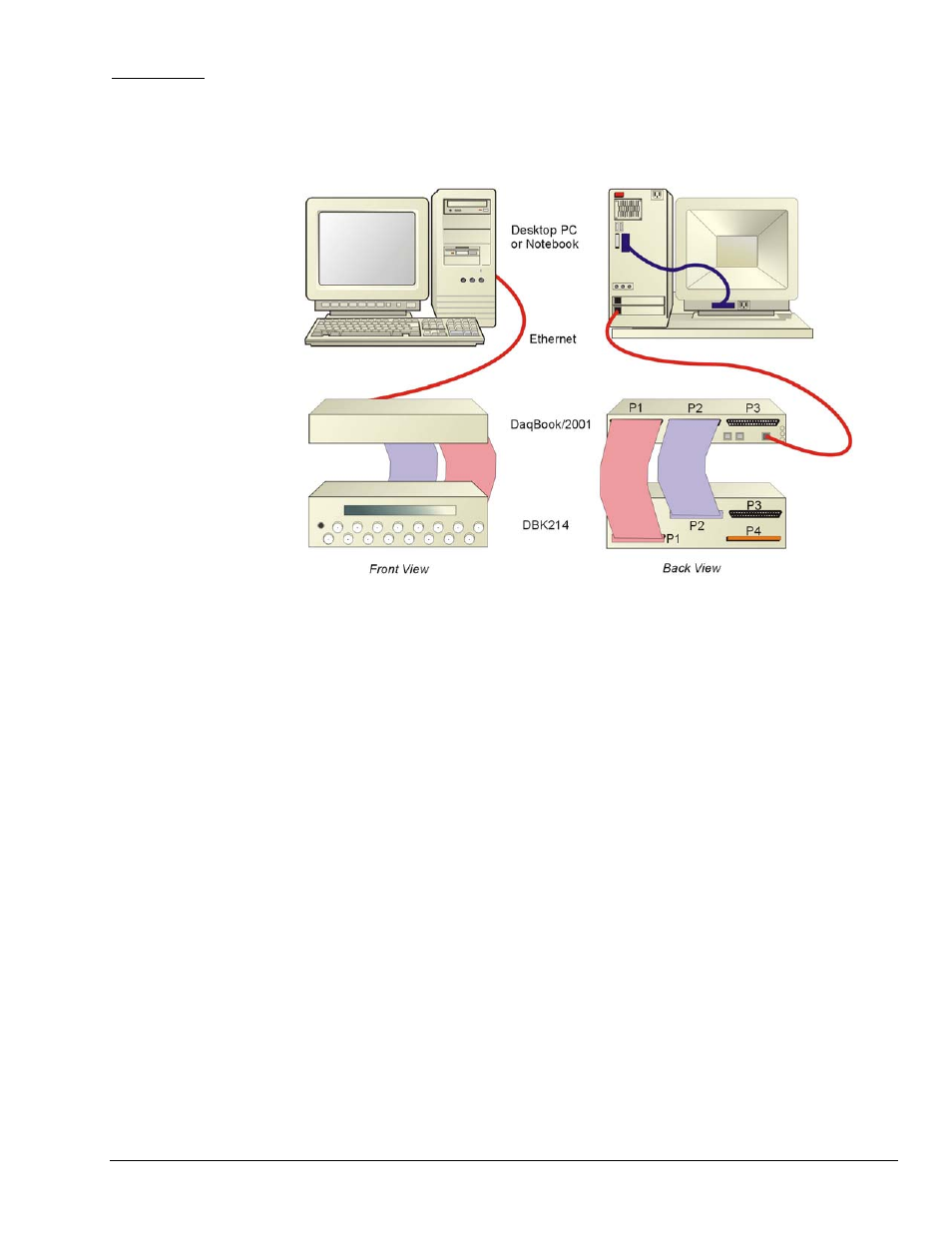
Example 2:
DBK214 Connected to a DaqBook/2001
Notes regarding the above system example:
1)
Either of two Ethernet cables can be used: CA-242 is a 1.5 ft cable; CA-242-7 is a 7 ft. cable.
2)
A CA-255 [or CA-37] cable is being used to connect the DBK214’s P1 connector to the P1 connector of the
DaqBook/2001.
3)
The DBK214’s P1 connector [rear panel, lower-left] connects to the internal screw-terminal board to which analog I/O
signals could be connected via wire. The wires would be routed out through the upper slots of the front panel. In
addition, BNC connectors (for channels 0 through 7) connect [through the printed circuit board] to the P1 terminal
blocks.
4)
A CA-255 [or CA-37] cable is used to connect the DBK214’s P2 connector to the DaqBook/2001 P2 connector.
5)
The DBK214’s P2 connector connects to the internal screw-terminal board, to which digital I/O signals could be
connected via wire. The wires would be routed out through the upper slots of the front panel.
DBK Option Cards and Modules
967894
DBK214, pg. 5