Measurement Computing DBK213 User Manual
Page 5
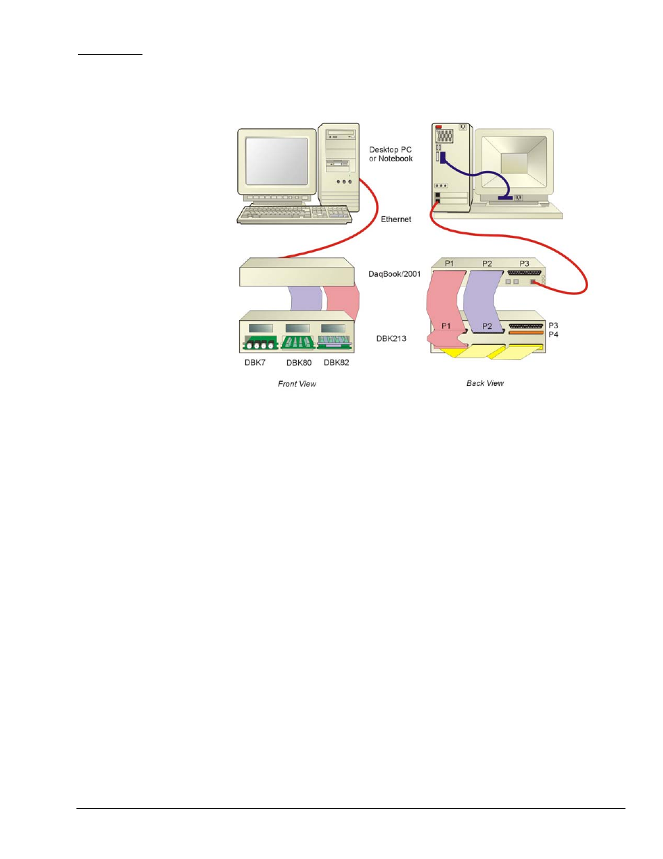
Example 2:
DaqBoook/2001
•
DBK7
•
DBK80
•
DBK82
-------- (3 Analog I/O Cards)---------
Notes regarding the above system example:
1)
Either of two Ethernet cables can be used: CA-242 is a 1.5 ft cable; CA-242-7 is a 7 ft. cable.
2)
In the illustration, DBK213 is housing a DBK7, DBK80, and DBK82. Each is an analog card that will make use of P1
in regard to analog signal I/O.
3) 1
st
P1 Cable (back view, bottom cable): A CA-37-3 cable is being used to link together to DB37 connectors of all
three analog DBK cards.
4) 2
nd
P1 Cable (back view, left cable): A CA-255-2T is being used to connect the other P1 cable and the DBK213’s P1
to the P1 connector of the DaqBook/2001.
5)
The DBK213’s P1 connector [rear panel, upper-left] connects to the internal screw-terminal board to which analog I/O
signals could be connected via wire. The wires would be routed out through the upper slots of the front panel.
6)
A CA-255 [or CA-37] cable is used to connect the DBK213’s P2 connector to the DaqBook/2001 P2 connector.
7)
The DBK213’s P2 connector connects to the internal screw-terminal board, to which digital I/O signals could be
connected via wire. The wires would be routed out through the upper slots of the front panel.
8)
In a different scenario, the DBK213’s P2 connector could be connected to digital DBK options instead of connecting
the P1 connector to analog DBK options as illustrated.
DBK Option Cards and Modules
969294
DBK213, pg. 5