Measurement Computing DBK202 Series User Manual
Page 5
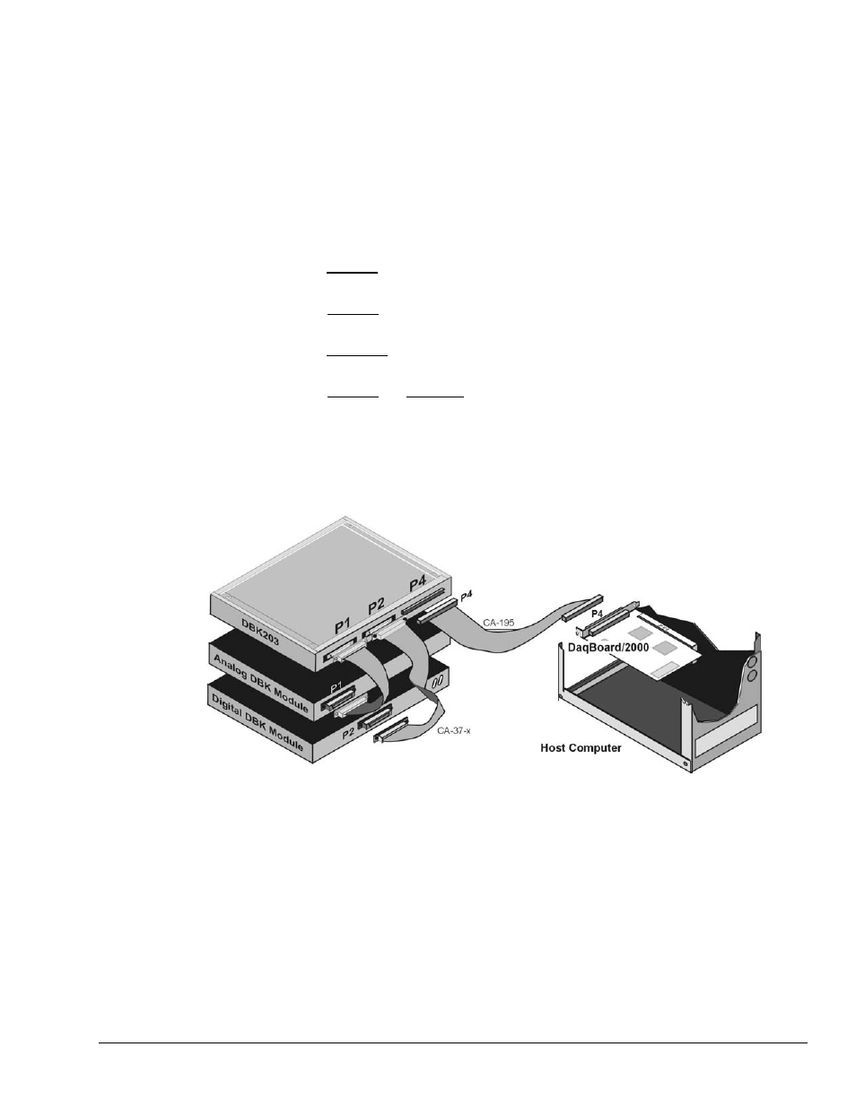
5. The board’s 100-pin P4 connector connects to the DaqBoard/2000 P4 connector via a
CA-195 Cable.
6. To obtain maximum protection from static, connect the CHASSIS terminal to earth ground.
Notes: Regarding connections to DB37 connectors and to the P3 (40-pin) header:
(a) P1 connects to an analog DBK card or module’s P1 connector via a CA-37 cable.
(b) P2 connects to a Digital DBK card or module’s P2 connector via a CA-37 cable.
(c) The 40-pin header (P3) connects to a Pulse/Frequency DBK card, or to a module’s
P3 connector via a CA-60 cable. Note that CA-60 cables have a 40-pin female
connector at one end and a DB37 (37-pin) male connector at the other end.
7. To access the board, i.e., to connect to P3 or to terminal blocks:
a) DBK202 – access of the board is direct, or as determined by your own custom
enclosure.
b) DBK203 – Loosen the two thumbscrews on the front panel and slide the card
drawer free of the unit.
c) DBK203A – Remove the upper inside screw from each of the four corner brackets
(see figure, page 2) and lift the cover plate from the unit.
d) DBK204 and DBK204c – Follow step 2b or 2c as applicable to your unit.
8. For DBK204 and DBK204c refer to the separate CE Cable Kit instructions that are included
with the associated CE cable kit.
Example of a DaqBoard/2000 System using a DBK203 (or DBK203A)
DBK Option Cards and Modules
938994
DBK202, DBK203, and DBK204 Series, pg. 5