Usb connector, Pull-up resistors, Power consumption – Measurement Computing USB-DIO24/37 User Manual
Page 13
USB-DIO24/37 User's Guide
Functional Details
13
USB connector
The USB connector provides +5 V power and communication. The voltage supplied through the USB connector
is system-dependent, and may be less than 5 V. No external power supply is required.
LED
The LED indicates the communication status of the USB-DIO24/37. It uses up to 5 mA of current and cannot be
disabled. The table below explains the function of the USB-DIO24/37 LED.
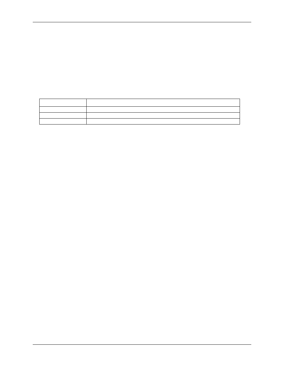
LED Illumination
LED status
Description
Steady green
The USB-DIO24/37 is connected to a computer or external USB hub.
Blinks continuously
Data is being transferred.
Blinks three times
Initial communication is established between the USB-DIO24/37 and the computer.
Pull-up resistors
Each digital port has an internal 47 kΩ pull-up resistor network. All digital pins are pulled up to +5 V (high
logic level) on power up and reset.
Power consumption
The maximum total output current that can be drawn from all USB-DIO24/37 connections (power and digital
outputs) is 500 mA. This maximum applies to most personal computers and self-powered USB hubs.
Bus-powered hubs and notebook computers may limit the maximum available output current to 100 mA.
Once you start running applications with the USB-DIO24/37, each DIO bit can draw up to 2.5 mA. The
maximum amount of +5V current available for external use, over and above that required by the USB-
DIO24/37, is the difference between the total current requirement of the USB-DIO24/37 (based on the
application), and the allowed current draw of the PC platform (500 mA for desktop PCs and self-powered hubs,
or 100 mA for bus-powered hubs and notebook computers).
With all outputs at their maximum output current, you can calculate the total current requirement of the USB-
DIO24/37 +5 V as follows:
(USB-DIO24/37 @ 40 mA) + (24 DIO @ 2.5 mA ea) = 100 mA
For an application running on a PC or powered hub, this value yields a maximum user current of
500 mA−100 mA = 400 mA. This number is the total maximum available current at the +5 output pins.
Measurement Computing highly recommends that you figure in a safety factor of 20% below this maximum
current loading for your applications. A conservative, safe user maximum in this case would be 320 mA.
Since laptop computers typically allow up to 100 mA, the USB-DIO24/37 in a fully-loaded configuration may
be above that allowed by the computer. In this case, you must determine the per-pin loading in the application
to ensure that the maximum loading criteria is met. The per-pin loading is calculated by simply dividing the
+5 V by the load impedance of the pin in question.