Analog voltage output terminals (vout0 to vout3), Analog current output terminals (iout0 to iout3), The screw terminal pins labeled – Measurement Computing USB-3102 User Manual
Page 15: Usb-3102 user's guide functional details, Vout0, Vout3, Iout0, Iout3
USB-3102 User's Guide
Functional Details
15
2
9
V
O
U
T
1
3
0
IO
U
T
1
3
1
V
O
U
T
3
3
2
IO
U
T
3
3
3
A
G
N
D
3
4
3
5
3
6
3
7
3
8
A
G
N
D
3
9
N
C
4
0
4
1
4
2
4
3
A
G
N
D
4
4
4
5
4
6
4
7
5
0
D
G
N
D
5
1
IT
E
S
T
5
2
C
T
R
5
3
D
G
N
D
5
4
D
IO
C
T
L
5
5
D
G
N
D
5
6
+
5
V
4
8
A
G
N
D
4
9
S
Y
N
C
L
D
N
C
N
C
N
C
N
C
N
C
N
C
N
C
N
C
N
C
N
C
N
C
V
O
U
T
0
1
IO
U
T
0
2
V
O
U
T
2
3
IO
U
T
2
4
A
G
N
D
5
A
G
N
D
1
0
A
G
N
D
1
5
A
G
N
D
2
0
D
IO
0
2
1
D
IO
1
2
2
D
IO
2
2
3
D
IO
3
2
4
D
IO
4
2
5
D
IO
5
2
6
D
IO
6
2
7
D
IO
7
2
8
6
7
8
9
1
1
1
2
1
3
1
4
1
6
1
7
1
8
1
9
N
C
N
C
N
C
N
C
N
C
N
C
N
C
N
C
N
C
N
C
N
C
N
C
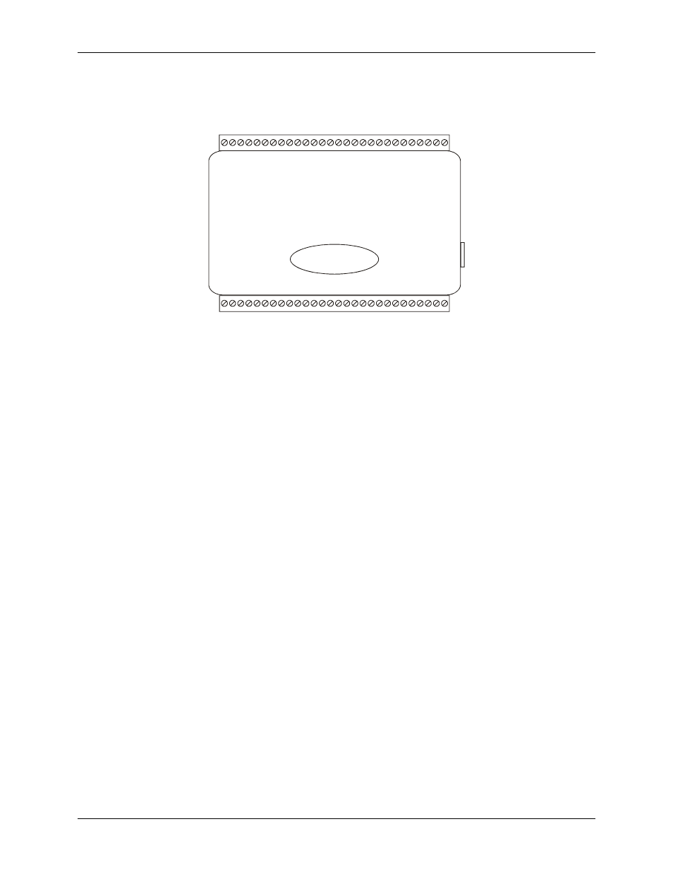
Figure 5. USB-3102 signal pin out
Analog voltage output terminals (VOUT0 to VOUT3)
The screw terminal pins labeled
VOUT0
to
VOUT3
are voltage output terminals (see Figure 5). The voltage
output range for each channel is software-programmable for either bipolar or unipolar. The bipolar range is
±10 V, and the unipolar range is 0 to 10 V.
Each D/A converter output controls a voltage and current channel pair simultaneously. When you write to a
voltage output, its associated current output is also updated. Each channel pair can be updated individually or
simultaneously.
Leave each pair of unused voltage and current outputs disconnected.
Analog current output terminals (IOUT0 to IOUT3)
The screw terminal pins labeled
IOUT0
to
IOUT3
are current output terminals (see Figure 5). The current range
for each channel is 0 to 20 mA.
Each D/A converter output controls a voltage and current channel pair simultaneously. When you write to a
current output, its associated voltage output is also updated. Each channel pair can be updated individually or
simultaneously. Leave each pair of unused voltage and current outputs disconnected.
Figure 6 shows a typical analog current output circuit. A minimum of 8 VDC must be available at IOUTn. A
maximum of 36 VDC external excitation voltage is used to power the loop. Consider the drop across the load
when selecting the supply voltage.
A typical application uses a 24 V loop supply. The loop can use either a grounded load where the supply floats,
or a grounded supply where the load floats. Each connection method is shown in Figure 6.