Timer outputs, Example: timer outputs, Using detection setpoints for output control – Measurement Computing USB-2527 User Manual
Page 42: What are detection setpoints
USB-2527 User's Guide
Functional Details
42
Each signal (A, B) can be connected as a single-ended connection with respect to the common digital ground
(GND). Both encoders can draw their power from the +5 V power output (pin 19) on the 68-pin SCSI
connector.
Connect each encoder’s power input to +5 V power. Connect the return to digital common (GND) on the same
connector. Make sure that the current output spec is not violated.
With the encoders connected in this manner, there is no relative positioning information available on encoder #1
or #2 since there is no Z signal connection for either. Therefore only distance traveled and velocity can be
measured for each encoder.
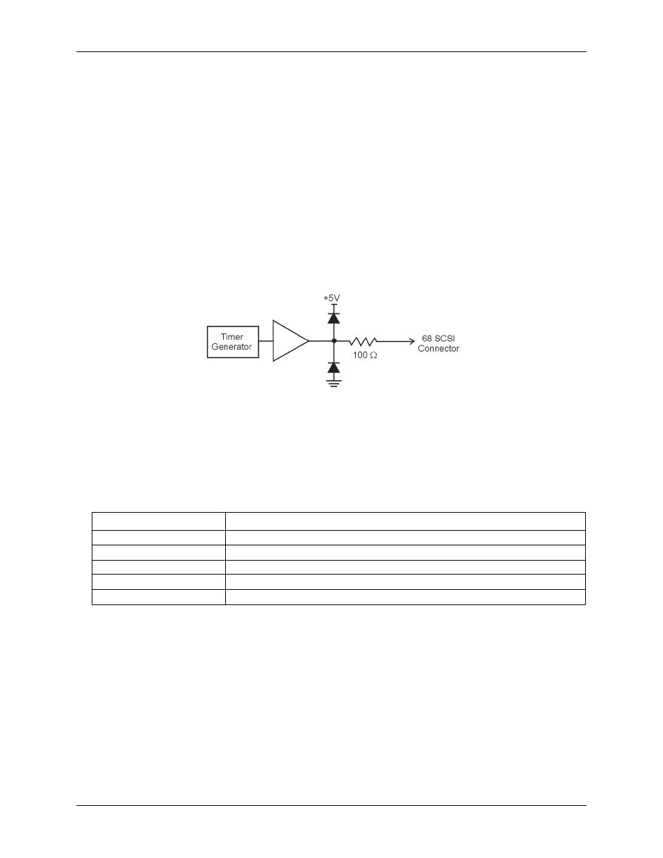
Timer outputs
Two 16-bit timer outputs are built into the USB-2527. Each timer is capable of generating a different square
wave with a programmable frequency in the range of 16 Hz to 1 MHz.
Figure 24. Typical USB-2527 timer channel
Example: Timer outputs
Timer outputs are programmable square waves. The period of the square wave can be as short as 1 µs or as long
as 65535 µs. Refer to the table below for examples of timer output frequencies.
Timer output frequency examples
Divisor
Timer output frequency
1
1 MHz
100
10 kHz
1000
1 kHz
10000
100 Hz
65535
15.259 Hz
The two timer outputs can generate different square waves. The timer outputs can be updated asynchronously at
any time.
Using detection setpoints for output control
What are detection setpoints?
With the USB-2527's setpoint configuration feature, you can configure up to 16 detection setpoints associated
with channels in a scan group. Each setpoint can update the following, allowing for real-time control based on
acquisition data:
FIRSTPORTC digital output port with a data byte and mask byte
analog outputs (DACs)
timers