Channel-gain queue, Analog output, Digital i/o – Measurement Computing USB-1208FS User Manual
Page 14: Pull-up/down configuration
USB-1208FS User's Guide
Functional Details
14
Channel-Gain queue
The channel gain queue feature allows you to set up a scan sequence with a unique per-channel gain setting and
channel sequence. The gain settings are stored in a channel-gain queue list that is written to local memory on
the device.
The channel-gain queue list can contain up to 16 elements in any order. The channel-gain queue list can contain
up to 16 elements in any order. An example of a four-element list is shown in the table below..
Sample channel-gain queue list
Element
Channel
Range
0
CH0
BIP10V
1
CH0
BIP5V
2
CH7
BIP10V
3
CH2
BIP1V
When a scan begins with the gain queue enabled, the USB-1208FS reads the first element, sets the appropriate
channel number and range, and then acquires a sample. The properties of the next element are then retrieved,
and another sample is acquired. This sequence continues until all elements in the gain queue have been selected.
When the end of the channel list is detected, the sequence returns to the first element in the list. This sequence
repeats until the specified number of samples is acquired.
Carefully match the gain to the expected voltage range on the associated channel or an over range condition
may occur. Although this condition does not damage the device, it does produce a useless full-scale reading,
and can introduce a long recovery time due to saturation of the input channel.
Analog output
You can connect up to two analog output connections to
D/A OUT 0
and
D/A OUT 1
. Each channel can be paced
individually at rates up to 10,000 updates per second. Both channels can be paced simultaneously using the
same time base at 5,000 updates per channel. The 0 V to 4.096 V output range provides a convenient 1 mV per
LSB when setting the output voltage levels.
Digital I/O
The device has 16 digital bits that are configured as two 8-bit ports (Port A and Port B). You can connect up to
eight digital I/O lines to each port (terminals
Port A0
to
Port A7
and
Port B0
to
Port B7
). Each port is
configurable as either input or output.
When configured for input, you can use the digital I/O terminals to detect the state of any TTL level input.
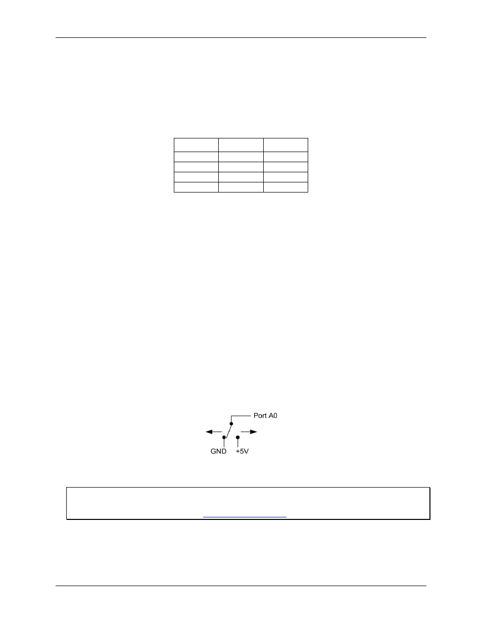
Refer to the schematic shown in Figure 8.
Figure 8. Schematic showing switch detection by digital channel Port A0
If you set the switch to the +5V input, DIO0 reads TRUE (1). When set to GND, Port A0 reads FALSE (0).
For more information on digital signal connections
For more information on digital signal connections and digital I/O techniques, refer to the Guide to DAQ Signal
Connections (available on our web site at
Pull-up/down configuration
Boards designed with hardware revision D and later have user-configurable internal jumpers to configure the
digital bits for pull-up (default) or pull-down. The hardware revision is listed with the part number on the
bottom of the device, for example P/N 193331D.