Installing the hardware, Connecting the board for i/o operations, Connectors, cables – main i/o connector – Measurement Computing PCI-QUAD04 User Manual
Page 10: Pinout – main i/o connector
PCI-QUAD04 User's Guide
Installing the PCI-QUAD04
10
Installing the hardware
After configuring the PCI-QUAD04, install the board in your computer. Follow the steps below.
Install the software before you install your board
The driver needed to run the PCI-QUAD04 is installed with the MCC DAQ software. Therefore, you need to
install the software package you plan to use before you install the hardware.
1. Turn your computer off and open it up.
2. Close your computer and turn it on.
A dialog box opens as the system loads, indicating that new hardware has been detected. If the information
file for this board is not already loaded onto your PC, you are prompted for the disk containing this file.
The Measurement Computing Data Acquisition Software CD supplied with your board contains this file. If
required, insert the disk or CD and click
OK
.
3. To test your installation and configure your board, run the InstaCal utility installed in the previous section.
Refer to the Quick Start Guide that came with your board for information on how to initially set up and
load InstaCal.
Connecting the board for I/O operations
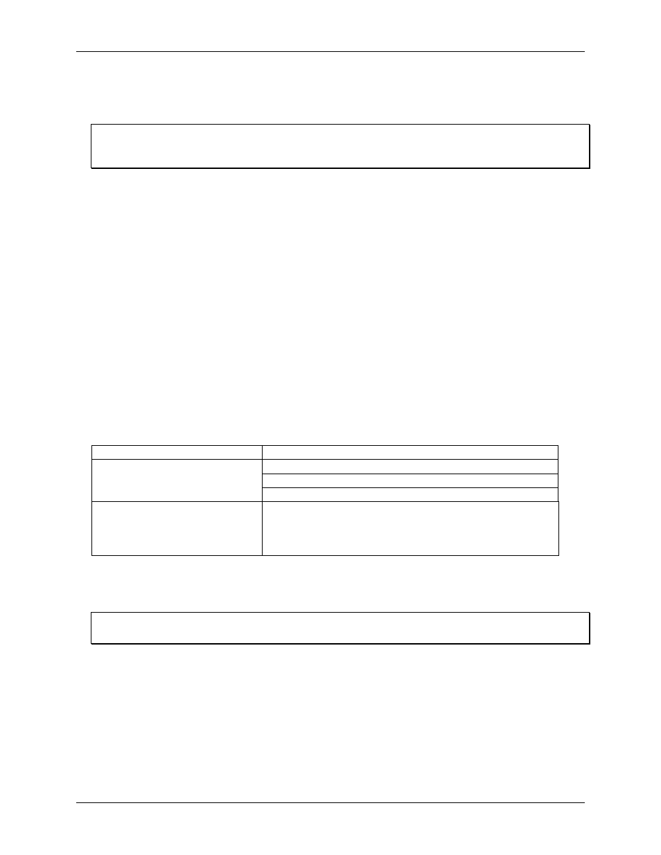
Connectors, cables – main I/O connector
The table below lists the board connector type, compatible cables, and compatible accessory products for the
PCI-QUAD04.
Board connectors, cables, and accessory equipment
I/O connector type
37-pin connector
Compatible cables
C37F-4X9F-1M
C37FF-x
C37FFS-x
Compatible accessory products
CIO-MINI37
CIO-MINI37-VERT
CIO-TERMINAL
SCB-37
Pinout – main I/O connector
Pin assignments of the 37-pin connector
P2
are shown in Figure 4.
Important
Be sure to correctly phase the encoder according to the manufacturer’s instructions.