Connecting the board for i/o operations, Connectors, cables – main i/o connector, Pin out – main i/o connector – Measurement Computing PCI-DIO24/S User Manual
Page 10
PCI-DIO24/S User's Guide
Installing the PCI-DIO24/S
10
Connecting the board for I/O operations
Connectors, cables
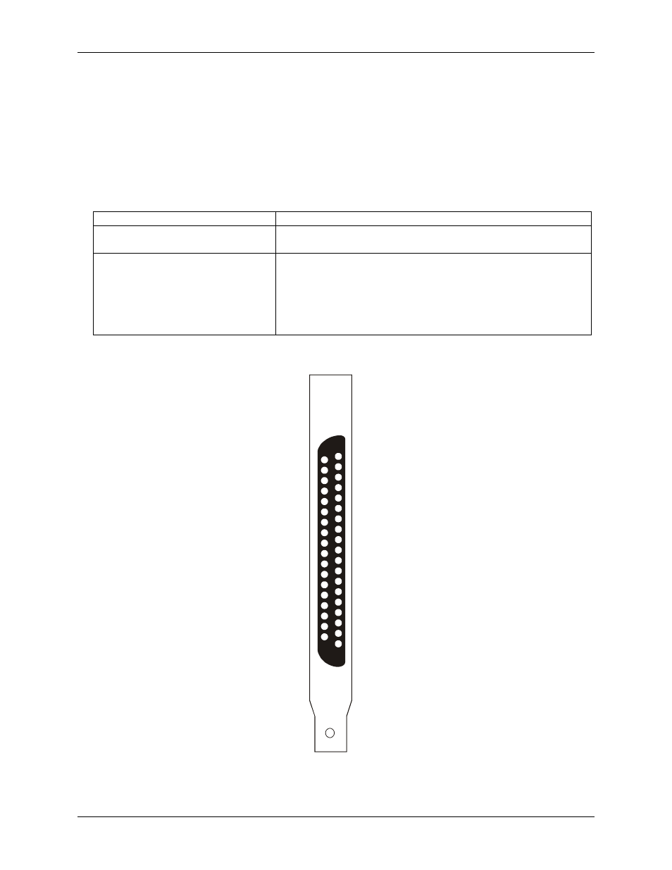
– main I/O connector
Table 2-1 lists the board connectors, compatible cables, and compatible accessory products for the PCI-
DIO24/S.
Table 2-1. Board connectors, cables, and accessory equipment
I/O connector type
CONN37DR male
Compatible cable
C37FFS-x, where x =5 or 10 feet (Figure 2)
C37FF-x, where x = length in feet (Figure 3)
Compatible accessory products (with the
C37FFS-x and C37FF-x cables)
CIO-MINI37, CIO-MINI37/DST
SCB-37
CIO-ERB24
CIO-ERB08
SSR-RACK24
SSR-RACK08
Pin out
– main I/O connector
1
IRQ_INPUT
2
IRQ_Enable
3
Port B7
4
Port B6
5
Port B5
6
Port B4
7
Port B3
8
Port B2
9
Port B1
10
Port B0
11
GND
12
N/C
13
GND
14
-12V
15
GND
16
+12V
17
GND
18
+5V
19
GND
+5V
20
GND
21
PORT C7
22
PORT C6
23
PORT C5
24
PORT C4
25
PORT C3
26
PORT C2
27
PORT C1
28
PORT C0
29
PORT A7
30
PORT A6
31
PORT A5
32
PORT A4
33
PORT A3
34
PORT A2
35
PORT A1
36
PORT A0
37
Figure 1. PCI-DIO24/S I/O connector pin out