Pinout – main i/o connectors, Cabling, Cio-dio96 user's guide installing the cio-dio96 – Measurement Computing CIO-DIO96 User Manual
Page 12: Figure 3. p1 and p2 pin out, Figure 4. c50ff-x cable
CIO-DIO96 User's Guide
Installing the CIO-DIO96
Pinout – main I/O connectors
The CIO-DIO96 connector has two standard 50-pin header connectors (P1 and P2) that are accessible through
the PC/AT expansion bracket.
Connect FIRSTPORT and SECONDPORT signals to connector P1. Connect THIRDPORT and
FOURTHPORT signals to connector P2.
GND
50
FIRSTPORTC Bit 0
48
FIRSTPORTC Bit 2
46
FIRSTPORTC Bit 4
44
FIRSTPORTC Bit 6
42
FIRSTPORTB Bit 0
40
FIRSTPORTB Bit 2
38
FIRSTPORTB Bit 4
36
FIRSTPORTB Bit 6
34
FIRSTPORTA Bit 0
32
FIRSTPORTA Bit 2
30
FIRSTPORTA Bit 4
28
FIRSTPORTA Bit 6
26
SECONDPORTC Bit 0
24
SECONDPORTC Bit 2
22
SECONDPORTC Bit 4
20
SECONDPORTC Bit 6
18
SECONDPORTB Bit 0
16
SECONDPORTB Bit 2
14
SECONDPORTB Bit 4
12
SECONDPORTB Bit 6
10
SECONDPORTA Bit 0
8
SECONDPORTA Bit 2
6
SECONDPORTA Bit 4
4
SECONDPORTA Bit 6
2
49
+5V
47
FIRSTPORTC Bit 1
45
FIRSTPORTC Bit 3
43
FIRSTPORTC Bit 5
41
FIRSTPORTC Bit 7
39
FIRSTPORTB Bit 1
37
FIRSTPORTB Bit 3
35
FIRSTPORTB Bit 5
33
FIRSTPORTB Bit 7
31
FIRSTPORTA Bit 1
29
FIRSTPORTA Bit 3
27
FIRSTPORTA Bit 5
25
FIRSTPORTA Bit 7
23
SECONDPORTC Bit 1
21
SECONDPORTC Bit 3
19
SECONDPORTC Bit 5
17
SECONDPORTC Bit 7
15
SECONDPORTB Bit 1
13
SECONDPORTB Bit 3
11
SECONDPORTB Bit 5
9
SECONDPORTB Bit 7
7
SECONDPORTA Bit 1
5
SECONDPORTA Bit 3
3
SECONDPORTA Bit 5
1
SECONDPORTA Bit 7
P1
GND
50
THIRDPORTC Bit 0
48
THIRDPORTC Bit 2
46
THIRDPORTC Bit 4
44
THIRDPORTC Bit 6
42
THIRDPORTB Bit 0
40
THIRDPORTB Bit 2
38
THIRDPORTB Bit 4
36
THIRDPORTB Bit 6
34
THIRDPORTA Bit 0
32
THIRDPORTA Bit 2
30
THIRDPORTA Bit 4
28
THIRDPORTA Bit 6
26
FOURTHPORTC Bit 0
24
FOURTHPORTC Bit 2
22
FOURTHPORTC Bit 4
20
FOURTHPORTC Bit 6
18
FOURTHPORTB Bit 0
16
FOURTHPORTB Bit 2
14
FOURTHPORTB Bit 4
12
FOURTHPORTB Bit 6
10
FOURTHPORTA Bit 0
8
FOURTHPORTA Bit 2
6
FOURTHPORTA Bit 4
4
FOURTHPORTA Bit 6
2
49
+5V
47
THIRDPORTC Bit 1
45
THIRDPORTC Bit 3
43
THIRDPORTC Bit 5
41
THIRDPORTC Bit 7
39
THIRDPORTB Bit 1
37
THIRDPORTB Bit 3
35
THIRDPORTB Bit 5
33
THIRDPORTB Bit 7
31
THIRDPORTA Bit 1
29
THIRDPORTA Bit 3
27
THIRDPORTA Bit 5
25
THIRDPORTA Bit 7
23
FOURTHPORTC Bit 1
21
FOURTHPORTC Bit 3
19
FOURTHPORTC Bit 5
17
FOURTHPORTC Bit 7
15
FOURTHPORTB Bit 1
13
FOURTHPORTB Bit 3
11
FOURTHPORTB Bit 5
9
FOURTHPORTB Bit 7
7
FOURTHPORTA Bit 1
5
FOURTHPORTA Bit 3
3
FOURTHPORTA Bit 5
1
FOURTHPORTA Bit 7
P2
Figure 3. P1 AND P2 pin out
All the digital inputs and outputs are TTL. Under normal operating conditions, the voltages on the I/O pins
range from near 0 volts for the low state, to near 5 volts for the high state. The voltages and currents of external
devices usually exceed these values. Because of this, external relays are usually employed to handle higher
current and voltage loads.
In addition to load matching, digital signal sources often need to be filtered or "de-bounced". Refer to the Guide
to Signal Connections for information on digital interfacing. This document is available at
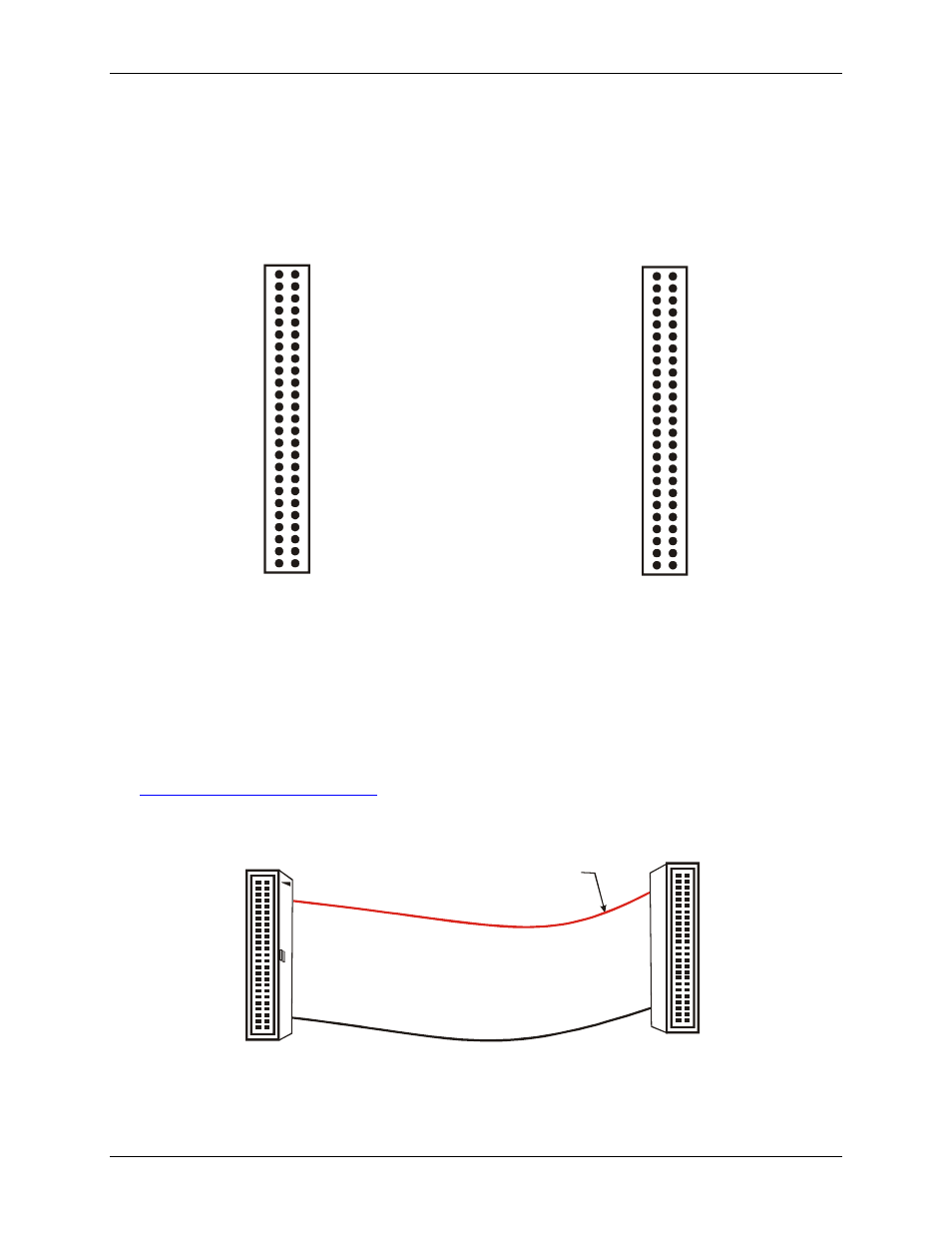
Cabling
The red stripe
identifies pin # 1
50-pin Female
IDC connector
50-pin Female
IDC Connector
1
2
49
50
2
50
1
49
Figure 4. C50FF-x cable
12