Wait state, Input type (v-i) – Measurement Computing CIO-DAS48-I User Manual
Page 10
CIO-DAS48-I User's Guide
Installing the CIO-DAS48-I
10
SW
A9
A8
A7
A6
A5
A4
A3
A2
HEX
200
100
80
40
20
10
08
04
9
8
7
6
5
4
3
2
9
8
7
6
5
4
3
2
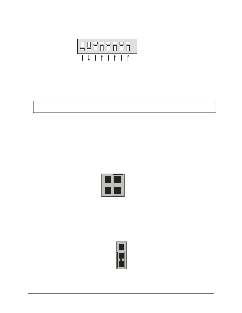
Figure 1. Base address switches
In the default configuration shown in Figure 1, addresses 9 and 8 are DOWN, and all others are UP.
Address 9 = 200 hex (512 decimal) and address 8 = 100 hex (256 decimal); when added together they equal
300 hex (768 decimal).
Disregard the numbers printed on the switch
When setting the base address, refer to the numbers printed in white on the printed circuit board.
Wait state
Enable the wait state jumper if you have a computer with an I/O bus transfer rate which is too fast for the CIO-
DAS48-I, or if the board fails sporadically in random ways.
To enable the wait state, set the jumper to the ON position. This jumper is OFF by default. Enabling the wait
state causes the personal computer's bus transfer rate to slow down whenever CIO-DAS48-I is written to or
read from. This jumper is shown in Figure 2 configured for OFF (wait state is disabled).
O
N
O
F
F
WAIT
STATE
Figure 2. Wait state jumper
Input type (V-I)
The jumper labeled
MODE V-I
sets the input type to either voltage (V) or current (I). The CIO-DAS48-I is
configured for current inputs, so set this jumper for
I
(Figure 3). Move the jumper from
V
to
I
only if you have
installed the CIO-DAS48-ISIP kit.
M
O
D
E
V
M
O
D
E
I
Figure 3. Input type jumper