Installation – Desa Twin Halogen Motion Sensing Light with 2-Level Lighting 5512 User Manual
Page 2
2
598-1275-00
INSTALLATION
For easy installation, select an existing light operated
by a wall switch for replacement.
For best performance, mount the fi xture about 8 ft. (2.4 m)
above the ground.
CAUTION: Keep the sensor at least 1" (2.5 cm)
away from the lamps.
❒ Place the Mounting Bolt through the front of the
junction box cover. Push the small gasket hole over
the Mounting Screw.
❒ Make sure the wire connectors and wires are inside
the junction box. Align the Mounting Screw with the
center hole in the Mounting Strap. Secure the fi xture
to the Mounting Strap.
M
OUNT
THE
L
IGHT
C
ONTROL
❒ Push the Rubber Plug fi rmly into place.
❒ If not installed on a weatherproof box, caulk the
wall plate and mounting surface with silicone
❒ Adjust the lamp holders by loosening the lock nuts
but do not rotate the lamp holders more than 180°
from the factory setting.
Keep lamps at least 1" (2.5
cm) from the sensor.
Black to Black
White to White
Gasket
Connect any fi xture ground wire(s) and the cover plate
ground screw to the junction box ground wire.
CAUTION: To Avoid Fire Or Burn Hazards:
• Allow fi xture to cool before touching. The bulb and the
fi xture operate at high temperatures.
• Keep fi xture at least 2" (5 cm) from combustible materi-
als. Do not aim at objects closer than 3 feet. (1 m).
• Use only T3, 150W (max.) tungsten halogen 120
VAC lamps.
W
IRE
THE
L
IGHT
C
ONTROL
WARNING: Turn power off at circuit breaker.
❒ Remove the existing light fi xture.
❒ Install mounting strap to junction box using screws
appropriate for your junction box.
❒ The plastic hanger can be used to hold the fi xture
while wiring. The small end of the plastic hanger
can be threaded through the hole in the center of
the cover plate. The small end then goes into one
of the slots on the mounting strap.
❒ Thread all fi xture wires through the large holes in
the gasket as shown.
❒ Connect the junction box wires to the light fi xture
wires as shown. Twist together and secure with
wire connectors.
Rubber Plug
Mounting
Bolt
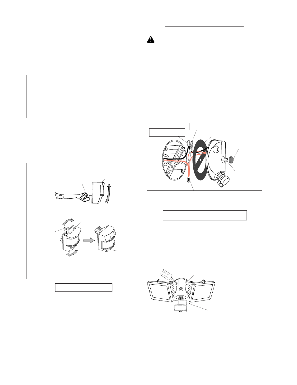
For eave mount only:
❒ Swing the sensor head towards the clamp screw
joint.
If the sensor pops out of the ball joint, loosen the
clamp screw and push the sensor back into the ball
joint. Tighten the clamp screw when done.
❒ Then rotate the sensor head clockwise 180° so
the controls face down.
Controls
For under eave installation, the sensor head must
be rotated as shown in the next two steps for proper
operation and to avoid the risk of electrical shock.
Also for proper under eave operation, remove the
protective backing from the Light Shield and stick on
as shown below.
Controls
Controls
Clamp Screw
Light Shield
Opening
B
ULB
I
NSTALLATION
NOTE: Lamps are included, but you will need to
install them
NOTE: When re-lamping, turn power off and let the
fi xture cool.
❒ Open glass covers. To remove the old bulb push the
bulb towards the right (with fi xture as shown) until
the left side of the bulb is clear of the left socket.
❒ To install a bulb, push the bulb into the right socket
so the bulb fi ts completely into the left socket.
❒ Check that the bulb is seated properly.
❒ Close the glass covers.
Push the Rubber Plug
over the mounting screw.