Field wiring, signal termination, and conditioning, Calibrating the cio-das08/jr-ao – Measurement Computing CIO-DAS08/JR-AO User Manual
Page 11
CIO-DAS08/JR-AO User's Guide
Installing the CIO-DAS08/JR-AO
11
37 DGND
36 DGND
35 +12V from PC bus
34 -12V from PC bus
33 5V from PC bus
32 5V from PC bus
31 D
7
30 D
6
29 DIN5
28 DIN4
27 DIN3
26 DIN2
25 DIN1
24 DIN0
23 AGND
22 AGND
21 AGND
20 AGND
IN
IN
37 PIN CONNECTOR
D/A 1 19
D/A 0 18
AGND 17
DOUT7 16
DOUT6 15
5 14
4 13
3 12
2 11
1 10
0 9
CH7 IN 8
7
6
5
4
3
2
1
DOUT
DOUT
DOUT
DOUT
DOUT
DOUT
CH6 IN
CH5 IN
CH4 IN
CH3 IN
CH2 IN
CH1 IN
CH0 IN
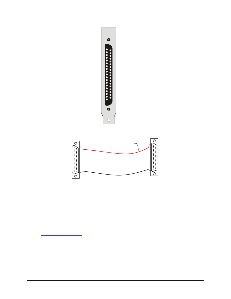
Figure 2. I/O connector pin-out
20
1
37
19
20
1
37
19
The red stripe
identifies pin # 1
Female connector
Female connector
Figure 3. C37FF-x cable
Field wiring, signal termination, and conditioning
You can use the following cabling, screw termination, and signal conditioning products with the CIO-
DAS08/JR-AO.
CIO-MINI37 – 37-pin screw terminal board. Details are available at
DFCON37 – Connector kit that includes a 37-pin female D-connector, D-shell, 37 crimp pins, and cable
termination kit to construct your own cable. Details are availa
CIO-LAB8-TERM – Experimentors Laboratory Screw Terminal Board for the DAS08 series.
Calibrating the CIO-DAS08/JR-AO
You can quickly calibrate the CIO-DAS08/JR-AO using InstaCal. The CIO-DAS08/JR has a fixed input range
and does not have any input amplification or gain/offset compensation electronics. When using the optional
Universal Library, all compensation for gain/offset errors is done in software after the signal is acquired. The
gain and offset calibration factors are stored in the CB.CFG configuration file and applied to the analog
samples after they are acquired. Run the
Calibrate
option from InstaCal to set the calibration factors.