Push, Ccb b, Ppb b c cr r – Marantz AV8003 User Manual
Page 19: Ppr r c cr r, Ppr r c cb b, Ppb b c cb b, Flasher, Flasher in in ir ir receiver receiver in in, Zone out, Zone out out out in in main main remote remote
SETUP
BASIC
OPERA
TION
ADV
ANCED
OPERA
TION
REMOTE
CONTROLLER
TROUBLESHOOTING
OTHERS
NAMES AND
FUNCTION
CONNECTIONS
ENGLISH
15
PUSH
PUSH
3
1
2
3
1
2
R
R
SR
SR
SL
SL
SW
SW
C
C
SBR
SBR
SBL
SBL
L
L
OUT
OUT
PUT
PUT
1
1
OUT
OUT
PUT
PUT
2
2
OUTPUT 1
OUTPUT 1
OUTPUT 2
OUTPUT 2
T 4
INPUT 4((DSS/VCR2
DSS/VCR2))
C
CB
B
//
P
PB
B
C
CR
R
//
P
PR
R
C
CR
R
//
P
PR
R
C
CR
R
//
P
PR
R
C
CB
B
//
P
PB
B
C
CB
B
//
P
PB
B
Y
Y
Y
Y
UT 1
INPUT 1(
(TV
TV)
)
INPUT 4
INPUT 4(
(DSS
DSS // VCR2
VCR2)
)
UT 3
INPUT 3(
(VCR1
VCR1)
)
INPUT 2
INPUT 2((DVD
DVD))
RS-232C
RS-232C
A
AC IN
IN
IN
OUT
OUT
IN
IN
OUT
OUT
ZONE
ZONE
OUT
OUT
DVD
DVD((2
2))
DSS/VCR2
DSS/VCR2(
(4
4)
)
VCR1
VCR1(
(3
3)
)
TV
TV(
(1
1)
)
MONI. OUT
MONI. OUT
2
2
1
1
FLASHER
FLASHER
IN
IN
IR
IR
RECEIVER
RECEIVER
IN
IN
UT
OUT
N
IN
1
1
2
2
EMITTER
EMITTER
OUT
OUT
DC OUT
DC OUT
R
R
L
L
CD/CDR BALANCED IN
CD/CDR BALANCED IN
OUT
OUT
L
L
E
TAPE
CD/CDR
CD/CDR
OUT
OUT
IN
IN
R
R
O
AUDIO
UNBALANCED
UNBALANCED
SR
SR
SL
SL
SBR
SBR
SBL
SBL
SW
SW
C
C
A
A
B
B
7.1CH
7.1CH
IN
IN
(
(AUX
AUX)
)
BALANCED
BALANCED
UNBALANCED
UNBALANCED
S-VIDEO
S-VIDEO
ZONE OUT
ZONE OUT
SELECTOR
SELECTOR
1
2
3
CONNECTION
GND
HOT(+)
COLD(-)
3
2
1
L
L
R
R
SR
SR
SL
SL
SBR
SBR
SBL
SBL
SW
SW
C
C
7.1CH
7.1CH
IN
IN
(
(AUX
AUX)
)
L
R
FRONT SURR. SURR.
BACK
SUB
WOOFER
CENTER
R
L
R
L
R
L
R L
R L
R L
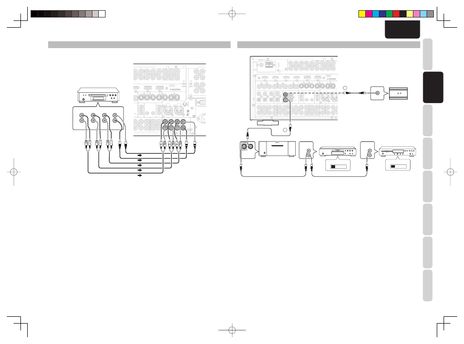
CONNECTING MULTI CHANNEL AUDIO COMPONENTS
The 7.1CH INPUT jacks are for multichannel audio source such as a Super Audio CD multichannel player,
DVD audio player or external decoder.
If you use these jacks, switch on the 7.1CH INPUT and set the 7.1CH INPUT level by using the SETUP MAIN
MENU. See page 23.
DVD Audio player
or
Super Audio CD
Multi channel player
PUSH
PUSH
3
1
2
3
1
2
FM
FM (
(75
75
Ω
Ω))
GND
GND
AM
AM
ANTENNA
ANTENNA
OU
OUT
PU
PUT
1
1
OU
OUT
PU
PUT
2
2
INPUT 3
INPUT 3((VCR1
VCR1))
OUTPUT 1
OUTPUT 1
OUTPUT 2
OUTPUT 2
INPUT 1
INPUT 1(
(TV
TV)
)
INPUT 4
INPUT 4((DSS/VCR2
DSS/VCR2))
INPUT 2
INPUT 2(
(DVD
DVD)
)
COMPONENT
COMPONENT
VIDEO
VIDEO
C
CB
B
//
P
PB
B
C
CR
R
//
P
PR
R
C
CR
R
//
P
PR
R
C
CR
R
//
P
PR
R
C
CB
B
//
P
PB
B
C
CB
B
//
P
PB
B
Y
Y
Y
Y
Y
Y
INPUT 1
INPUT 1(
(TV
TV)
)
INPUT 4
INPUT 4(
(DSS
DSS // VCR2
VCR2)
)
INPUT 3
INPUT 3(
(VCR1
VCR1)
)
INPUT 2
INPUT 2((DVD
DVD))
IN
IN
OUT
OUT
IN
IN
OUT
OUT
OUT
OUT
IN
IN
IN
IN
OUT
OUT
MONITOR
MONITOR
OUT
OUT
DVD
DVD(
(2
2)
)
DSS/VCR2
DSS/VCR2(
(4
4)
)
TV
TV(
(1
1)
)
ZONE
ZONE
OUT
OUT
VCR1
VCR1(
(3
3)
)
DVD
DVD((2
2))
DSS/VCR2
DSS/VCR2(
(4
4)
)
VCR1
VCR1(
(3
3)
)
TV
TV(
(1
1)
)
MONI. OUT
MONI. OUT
2
2
1
1
FLASHER
FLASHER
IN
IN
IR
IR
RECEIVER
RECEIVER
IN
IN
6
6
COAX.
COAX.
5
5
4
4
OUT
OUT
IN
IN
1
1
2
2
EMITTER
EMITTER
OUT
OUT
DC OUT
DC OUT
DIGITAL IN
DIGITAL IN
DIGITAL OUT
DIGITAL OUT
MAIN
MAIN
ZONE
ZONE
R
R
L
L
REMOTE
REMOTE
CD/CDR BALANCED IN
CD/CDR BALANCED IN
OUT
OUT
R
R
OUT
OUT
L
L
TAPE
TAPE
CD/CDR
CD/CDR
OUT
OUT
IN
IN
IN
IN
R
R
OUT
OUT
L
L
DSS/VCR2
DSS/VCR2
AUDIO
AUDIO
TV
TV
IN
IN
SR
SR
VCR1
VCR1
IN
IN
DVD
DVD
SL
SL
SBR
SBR
SBL
SBL
S
SW
C
A
A
B
B
(
(AUX
AUX)
)
3
3
2
2
1
1
OPT.
OPT.
VIDEO
VIDEO
S-VIDEO
S-VIDEO
ZONE OUT
ZONE OUT
OUT
OUT
IN
IN
MAIN
MAIN
REMOTE
REMOTE
REMOTE
CONTROL
REMOTE
CONTROL
IN
OUT
IN
OUT
EXTERNAL INTERNAL
EXTERNAL INTERNAL
1
RC OUT
2
8CH POWER AMPLIFIER MM8003
8CH POWER AMPLIFIER MM8003
POWER ON/OFF
POWER ON/OFF
STANDBY
STANDBY
REMOTE CONTROL
REMOTE CONTROL
OUT
OUT
IN
IN
CONNECTING THE REMOTE CONTROL JACKS
DVD player
MM8003
q
You can control other Marantz products through this
unit with the remote controller by connecting the
REMOTE CONTROL terminals on each unit.
The signal transmitted from the remote controller
is received by the remote sensor on this unit. Then
the signal is sent to the connected device through
this terminal. Therefore you need to aim the remote
control only at the unit. Also, if a Marantz power
amplifi er (some models excluded) is connected to
one of these terminals, the power amplifi er’s, power
switch is synchronized with this unit’s power switch.
To make REMOTE CONTROL connections with
an MM8003, set P.AMPLINK to ENABLE. To make
REMOTE CONTROL connections with another
power amp, set P.AMPLINK to DISABLE. (See page
34)
Set the REMOTE CONTROL SWITCH on the back of
other units (not the AV8003) to “EXT.” (EXTERNAL) to
use this feature.
CD player
OPTION
w
Whenever external infrared sensors or similar devices
are connected to RC-5 IN of the unit, be sure to
always disable operation of the infrared sensor on the
unit by using the following procedure.
1.
Hold down the ZONE button and the MENU
button on the front panel at the same time for
fi ve seconds.
2.
The setting “IR=ENABLE” is shown on the FL
DISPLAY.
3.
Press
the
CURSOR buttons (
1
,
2
) to change
this to “IR=DISABLE”.
4.
Press
the
ENTER button. Once this setting
is made, the infrared sensor on the unit is
disabled.
Note:
• Be sure to set to “IR=ENABLE” when external
infrared sensors or similar devices are not connected.
Otherwise, the unit will be unable to receive remote
control commands.
5.
To restore the original setting, perform steps 1
to 4 to set to “IR=ENABLE”.
AV8003N.indb 15
AV8003N.indb 15
08.4.28 10:49:14 AM
08.4.28 10:49:14 AM