Window one - adapter, Status and settings for sample clock, digital i/o – Lynx Studio LynxTWO Macintosh Mixer Addendum User Manual
Page 2
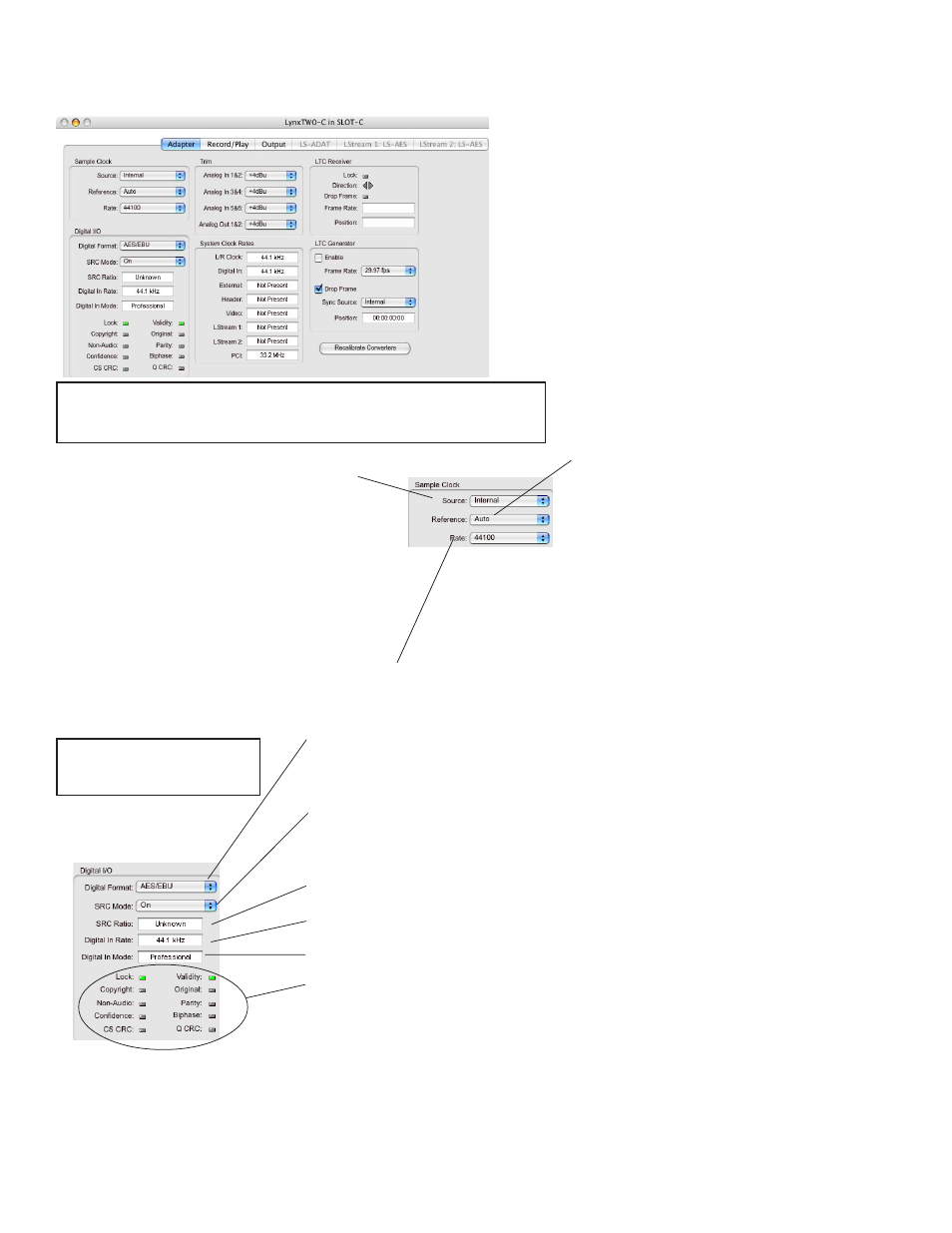
Sample Clock - Provides control of the Sample Clock and reference. All LynxTWO
audio devices on a single card MUST have identical sample rates. Clock Source and
sample rates cannot be changed when LynxTWO is playing or recording.
Rate
: Displays the current sample rate of the LynxTWO.
Available rates are:
11025, 16000, 22050, 32000, 44100,
48000, 88200, 96000, 176400, 192000, 200000
Digital I/O: Sets and displays the
formats, modes and status of the
digital audio input and output.
Digital Format
:
Allows selection of AES/EBU or S/P DIF format for input and output.
SRC Mode
:
Sample Rate Conversion Mode
On
(default):
SRC enabled on digital input.
Off: Clock Sync
: SRC disabled, sample clock source set to source other than Digital.
Off
:
SRC disabled, sample clock source set to Digital.
On: Digital Out
:
SRC enabled on Digital Output. Requires a valid signal on the Digital In to clock
the Digitial Output. Digital Input is muted.
SRC Ratio
:
Indicates Sample Rate Conversion Ratio when in “SRC On” mode.
Digital In Rate
:
Measured rate of incoming digital signal.
Digital In Mode
: Indicates Professional or Consumer input status.
LED Indicators
: Red and/or Green indicators for:
Lock
:
Red - Receiver PLL not locked; Green - Receiver PLL locked.
Validity
:
Green - Channel status validity bit set.
Copyright
:
Green - SCMS copyright bit set (consumer mode).
Original
:
Green - SCMS original bit set (consumer mode).
Non Audio
:
Green - Channel status non-PCM bit is set, e.g. Dolby Digital, DTS.
Parity
:
Red - Parity error detected.
Confidence
:
Red - Signal quality degraded.
Biphase
:
Red - Bi-phase coding error detected.
CS CRC
:
Red - Channel Status CRC error detected.
Q CRC
:
Red - Q Channel subcode data CRC detected.
Source
:
Internal:
Clock derived from the on-board crystal
oscillator.
Digital:
Clock signal from the DIGITAL IN connector
on the L2Sync cable.
External:
Clock signal from the SYNC IN connector on
the L2Sync cable.
Header:
Clock signal from the board-mounted CLOCK
IN header.
Video:
NTSC or PAL composite video signal from the
SYNC IN connector on the L2Sync cable.
LStream1:
Clock signal from the LStream port on the
L2Sync connector.
LStream2:
Clock signal from the LStream port on
the board mounted header.
Reference:
Provides selection of the clock source
reference type from one of the following:
Auto:
Automatic selection. Valid for Internal,
Digital, and Video clock sources.
13.5MHz:
13.5MHz video dot clock. Valid for
External and Header clock sources.
27MHz:
27MHz video dot clock. Valid for External
and Header clock sources.
Word:
Word clock. Valid for External, Header,
and LStream clock sources.
Word256:
256X word clock (Super Clock). Valid for
External and Header clock sources.
Window One - Adapter
Status and Settings for Sample Clock, Digital I/O
Continued on the next page...