Model dcs, Installation and operating instructions – Louroe Electronics DCS User Manual
Page 3
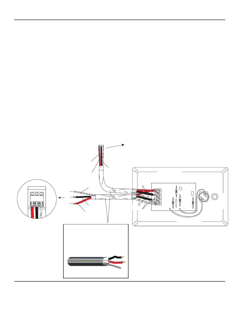
CONNECTING MODEL DCS DIRECTLY TO LOUROE MICROPHONE AND A BASE STATION
I WIRING CONNECTION TO MICROPHONE
A 3-pin terminal block is located on the back of the microphone housing, marked A, B, C
A represents +12Vdc
B represents Audio (Microphone Output)
C represents Ground
If using West Penn 452 or equivalent with same color code, connect:
Red wire (12Vdc) to terminal A of microphone terminal block
Black wire (Audio Out) to terminal B of microphone terminal block
Bare wire (Ground) to terminal C of microphone terminal block
II WIRING CONNECTION BETWEEN MICROPHONE AND DCS
Model DCS has a 4-pin terminal block on backside of face plate marked 1, 2, 3, 4
Bring other end of cable to DCS and connect as follows:
Bare wire connects to Pin 1 of DCS
Black wire connects to Pin 2 of DCS
Red wire connects to Pin 4 of DCS
III WIRING CONNECTION FROM MODEL DCS TO LOUROE SOUND ACTIVATED BASE STATION
Wiring requirements - West Penn 452 (same as used in step 1)
Bare wire connects to Pin 1 of DCS (shared with bare wire from microphone)
Black wire connects to Pin 3 of DCS
Red wire connects to Pin 4 of DCS (shared with red wire from microphone)
C
2
B
3
A
4
3-PIN BLOCK OF
LOUROE
MICROPHONE
MODEL DCS
BLACK
BLACK
BLACK
BARE
RED
BARE
RED
BARE
RED
2 Conductor shielded cable, 22
gauge with a 24 gauge drain wire
NOTE:
Unshielded cable is not
satisfactory for audio systems
WIRING REQUIREMENTS
West Penn 452 or equivalent
1
TO TERMINAL BLOCK OF
LOUROE DG SERIES BASE
STATION
REFER TO THE SPECIFIC BASE
STATION
INSTALLATION INSTRUCTIONS
FOR PROPER
CONNECTIONS
ALL LOUROE MICROPHONES
ARE COMPATIBLE
WITH MODEL DCS
NOTE: If using wiring with a different
color code, be sure they are
properly matched between the
microphone and Model DCS.
A B C
INSTALLATION AND OPERATING INSTRUCTIONS
Page 3 of 4
LOUROE ELECTRONICS 6 9 5 5 VA L J E A N AVENUE, VAN NUYS, CA 91406
TEL (818) 994-6498
FAX
994-6458
website: www.louroe.com e-mail: [email protected]
(818)
®
dcs_inst_3/15