Interconnection diagram, Installation and operating instructions – Louroe Electronics TLO-NM User Manual
Page 3
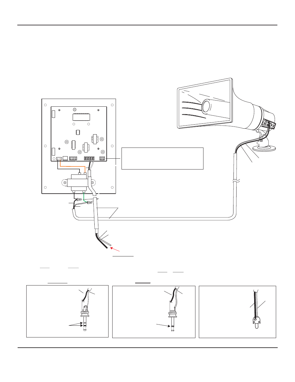
INTERCONNECTION DIAGRAM
LOUROE MODEL AOP-SP70 SPEAKERPHONE CONVERSION UNIT,
AND LOUROE MODEL TLO-NM 70V SPEAKER
CONNECTION TO
DVR, IP NETWORK CAMERAS OR VIDEO SERVER
(ONE WAY TALKBACK ONLY)
INSTALLATION AND OPERATING INSTRUCTIONS
Page 3 of 4
LOUROE ELECTRONICS™ 6 9 5 5 VA L J E A N AVENUE, VAN NUYS, CA 91406
TEL (818) 994-6498
FAX
994-6458
website: www.louroe.com e-mail: [email protected]
(818)
For connection to DVR, IP Network Camera, etc., solder the appropriate plug (RCA, 3.5mm
mono or 3.5mm stereo) to match the audio inputs of the receiving device as shown below.
Refer to IP Camera’s instruction to determine if 3.5mm audio is mono or stereo
Audio Out
Audio Out
RCA CONNECTION
3.5mm MONO CONNECTION
3.5mm STEREO CONNECTION
White Wire
Black Wire
Black Wire
White Wire
M
O
N
O
S
T
E
R
E
O
Audio Out
Black Wire
White Wire
EXT
SPKR
SPKR
SPKR
EXT
A B C
Vdc
+12
GND
+
WHITE
WIRE NUTS
2 COND 18 AWG CABLE
(OBSERVE COLOR CODING)
BLACK
BLACK SPEAKER
(GROUND)
WHITE SPEAKER
(POSITIVE)
LOUROE MODEL AOP-SP70
C
A
SP
B
WHITE (SP)
BLACK (C)
TO AUDIO OUT OF IP CAMERA, ENCODER, DVR, ETC.
Using power supply (included), connect as follows:
Positive 12Vdc connects to terminal marked “+”
Negative 12Vdc or ground connects to terminal
marked “GND”( wire with white stripes)
tlo-nm inst 3/15