Step 4, Step 3, Installation instructions – DCS DS224 User Manual
Page 8
SINGLE
MODELS
ONLY
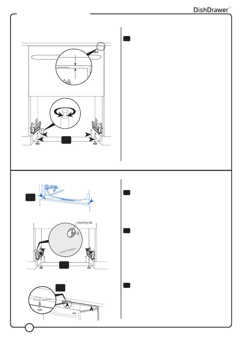
Check the position of the chassis is still where marked on the cavity,
before securing the product.
There are four
5
/
8
” (16mm) round holes, two on the left and two on
the right hand side in the sound insulation. These provide access to
the mounting tabs.
To secure the product to the cabinetry use a
5
/
8
” (16mm)
Phillips screw in each mounting tab.
Make sure the sound insulation is positioned correctly before
continuing installation.
DOUBLE MODELS ONLY
Screw the two top tabs to the underside of bench. Use the supplied
Phillips
5
/
8
” (16mm) screws. Tabs can accommodate a maximum of
3
/
4
” (19mm) vertical gap.
DOUBLE MODELS ONLY
Adjust the height of the product to suit the cabinetry, by turning the
feet from inside the product using a wrench or M5 socket.
TIP - gently take the load off each foot using the slide and
then turn by hand.
NOTE: For integrated products, the upper panel may be
aligned with the top of the adjacent cabinetry, provided
a minimum
3
/
16
”
(5mm)
clearance from the counter is
maintained.
Important!
The product must be levelled to within
3
/
32
” (2.5mm) from front to
back, and side to side.
Important!
The product should NOT support any part of the kitchen cabinetry.
TIP - Place a spirit level on the drawer runners to level the
product.
R
INSTALLATION INSTRUCTIONS
STEP 4:
SECURING THE PRODUCT
STEP 3:
ADJUSTING THE FEET
(DOUBLE MODELS ONLY)
11
12
13
11
12
13
8
10
10
3
/
16
”
(5mm)