Introduction, Figure 1 block diagram – Kussmaul Electronics 091-139-2-12 User Manual
Page 2
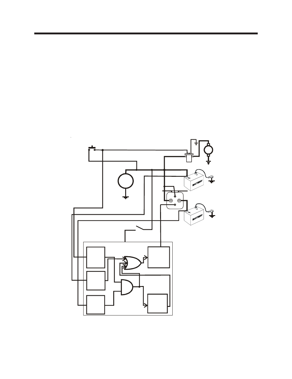
The Model 091-139-2-12 AUTO ISOLATOR I system is a lossless isolator replacement for the
conventional diode isolator. Designed to be installed in a vehicle with one or more Main
batteries that must be isolated from one or more auxiliary batteries. The system consists of
a voltage detector and controller Model 091-139-CONT-12 and a separate 200-ampere rated
solenoid, Model 091-139-SOL-12HO for switching the batteries. In addition to maintaining
battery isolation the AUTO ISOLATOR I may parallel the batteries on engine starting if the
auxiliary battery has sufficient charge to assist in the cranking. A block diagram of the system
appears in figure 1.
INTRODUCTION
AL
T
E
R
N
A
T
O
R
MAIN
BATTERY
AUXILIARY
BATTERY
PARALLELING
SOLENOID
STARTER
SOLENOID
STARTER
PUSH BUTTON
MAIN
BATTERY
VOLTAGE
DETECTOR
AUX.
BATTERY
VOLTAGE
DETECTOR
STARTER
ISOLATOR
SOLENOID
DRIVER
PO
WER
IGNITION
SWITCH
TIMER
Figure 1
Block Diagram
MAIN BATTERY SENSE
AUXILIARY BATTERY SENSE