Kussmaul Electronics 091-32-029 User Manual
Kussmaul electronics company, inc
M
O
C
C
.N
.
O
.N
.
RELAY 1
DS1
R1
1R
C
R2
C R3
DS2
1
2
3
S
W
IT
C
H
1
S
W
IT
C
H
2
+ VOLTS
RELAY LOAD CONTACTS, TYPICAL
CONNECT LOADS AS REQUIRED
LOAD NOT TO EXCEED 30 AMPERES
M
O
C
C
.N
.
O
.N
.
RELAY 2
2R
C
K1
K2
M
O
C
C
.N
.
O
.N
.
RELAY 1
DS1
R1
1R
C
R2
C R3
DS2
1
2
3
+ VOLTS
RELAY LOAD CONTACTS, TYPICAL
CONNECT LOADS AS REQUIRED
LOAD NOT TO EXCEED 30 AMPERES
M
O
C
C
.N
.
O
.N
.
RELAY 2
2R
C
K1
K2
S
W
IT
C
H
1
S
W
IT
C
H
2
KUSSMAUL ELECTRONICS COMPANY, INC.
170 CHERRY AVENUE, WEST SAYVILLE, NEW YORK, 11796-1221 USA
SINCE 1967, DESIGNERS OF INNOVATIVE PRODUCTS
Phone: Toll
Free: Fax: E-Mail:
,
Web:
631 567-0314,
800 346-0857,
631 567-5826,
www.kussmaul.com
File: 091-32-029( )-XX.pmd
Date: March 23, 2007, MFG
INSTALLATION INSTRUCTIONS
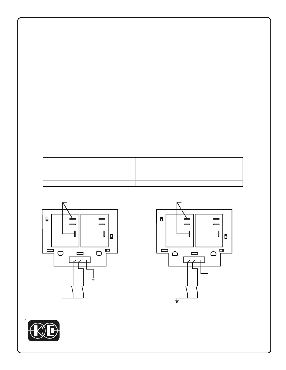
Model 091-32-029( )-XX, 2 Relay Board
The 091-32-029( )-XX Relay Board contains 2 relays mounted in a single assembly
along with indicating LED’s and suppression diodes across each relay coil. The as-
sembly is available for either 12 or 24 volt systems and for operation by supplying +12
volts to the relay or by grounding the relay. The table below outlines the part numbers,
voltages and wiring configuration.
Installation is simple and consists of mounting the base in a suitable location. The
common terminal is connected to either the vehicle Ground or to + voltage dependng
on the model. Inputs are supplied to the other two inputs. When the relays are ener-
gized the adjacent LED lights. The relays have 30 amp contacts which are accessible
through 1/4 inch quick disconnect terminals. Both normally open and normally closed
contacts are provided for complete circuit flexibility.
“P” Assembly
“N” Assembly
Part Number
Voltage
Common Connection
Input to Operate
091-32-029N-12
+ 12 Volts
+ 12 Volts
Ground
091-32-029P-12
+ 12 Volts
Ground
+ 12 Volts
091-32-029N-24
+ 24 Volts
+ 24 Volts
Ground
091-32-029P-24
+ 24 Volts
Ground
+ 24 Volts