Introduction to switch assembly & operation – Kreg PRS3100 Multi-Purpose Router Table Switch User Manual
Page 2
Introduction to Switch
Assembly & Operation
1. Make sure the switch and your router are disconnected
from any electrical outlets or extension cords.
2. Locate the two (2) 10-32x1/2” Pan Head Screws and
two (2) 10-32 Hex Nuts.
NOTE:
Some routers feature a special “LOCK-ON” type
feature which will not permit the router to be activated by the
switch. Y
ou may bypass this feature if your router manual
allows it. If not, you will still be able to “SHUT OFF” the
router with the switch.
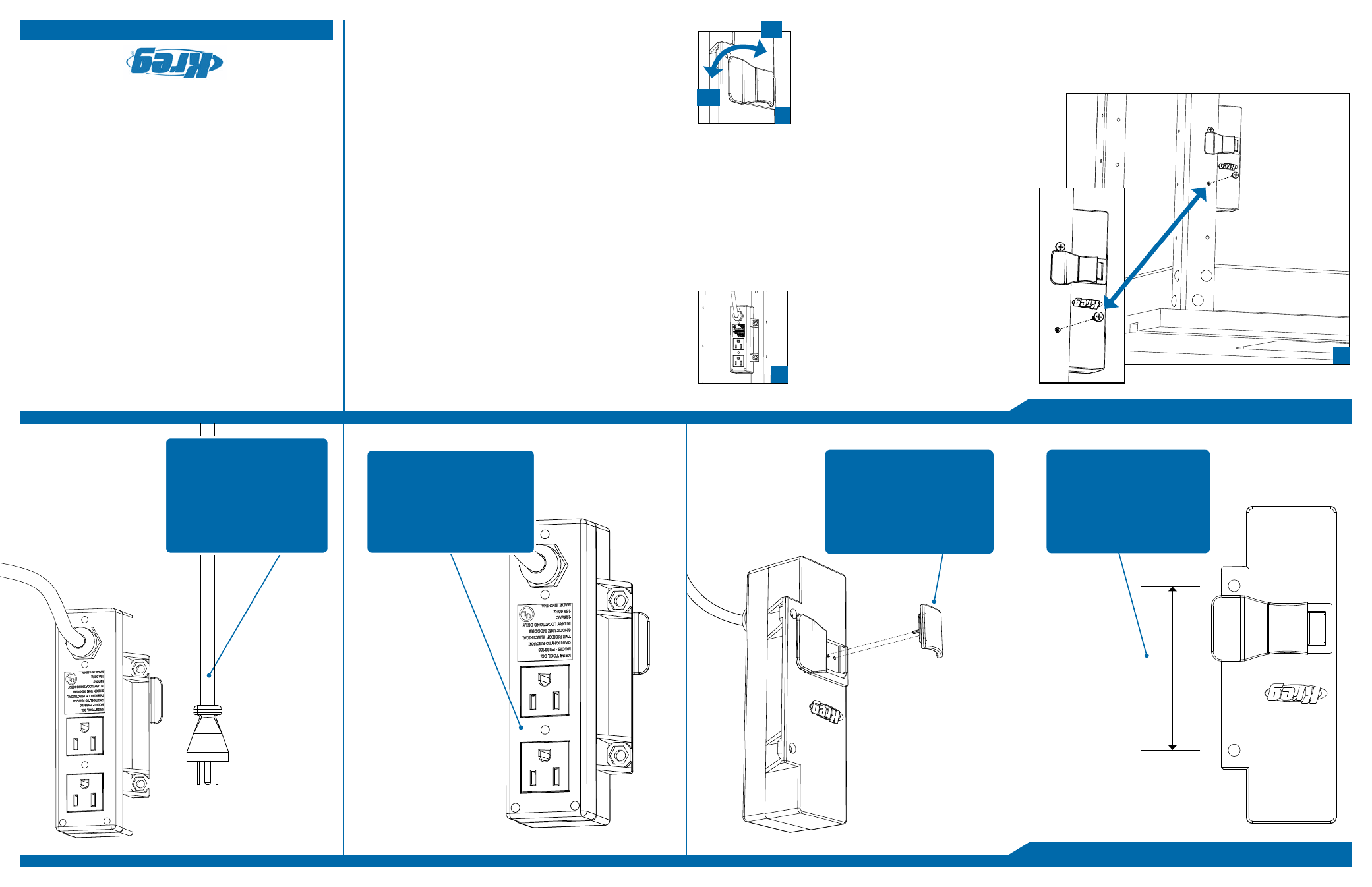
3. Position the Router Switch behind the
Router T
able’s steel stand
(as shown in Fig. A
& B)
and insert the two screws
from the front side. Secure the screws
in place by threading on the two hex
nuts and tightening down.
4. If your router is attached to your
router table, remove the bit and lower the collet assembly
below the table-top.
5. Plug your router into one of the outlets on the back side of
the switch and coil the excess cord, securing it together so it
does not hang loose from the table. Do allow some slack
however, so that the cord does not stretch.
6. If desired, you may also plug in an additional accessory
(such as a vacuum) to the second outlet on the back side of
the
switch.
7. Ensure that the switch is turned to
the “off position”
(as shown in Fig. C).
15. The router switch is designed for quick “turn-of
f”. To
do so,
use either your hand or your knee to depress the switch
again into the “OFF Position”.
16. When the router table is not in use, toggle the switch to the
“OFF Position” and remove the Key-Lok™. Store the
Key-Lok™ in a secure location where it is not available to
children and unplug the power cord from the wall.
(as shown in Fig. C).
8. Run the switch’
s power cord to your outlet or extension
cord, being careful to coil and secure any excess length
where possible. Do NOT plug it in. (Make sure the outlet
you will be using has a three-prong setup which was
professionally installed and has all proper grounding
and
insulation)
9. Make sure that the extension cord is not plugged into an
electrical
outlet.
10. Insert the Key-Lok™ fully until it ‘snaps’
into place. The
switch should be in the “OFF Position.”
11.
Make sure that your router is set to the “OFF Position” as well.
12. Plug the power cord into the 3-prong wall outlet or
extension
cord.
13. T
oggle your router to the “ON Position”. The router should
not engage since the switch is still set to the “OFF Position.”
14. V
erify that there are no foreign objects near the router
opening and that the router is fully secured and prepared to
run. If it is, you may test the switch by pulling the router
switch into the “ON Position.”
2-Plug Design allows for
router to be paired with
vacuum system and engaged
simultaneously with router. Use
only 3-prong plugs with proper
grounding and insulation.
Easily removable Key-Lok™
prevents switch from
unintentionally engaging.
Always remove Key-Lok™
when machine is not in use for
an extended period of time.
3-1/4” hole spacing designed
for use with Kreg Precision
Routing Equipment. Attach
by inserting the included pan
head screws and locking into
place with included hex nuts.
3-1/4”
B.
Heavy-Duty 8 foot, 14
gauge, power cord. Only
use a 14 gauge (or heavier)
three wire extension cord.
Only plug into 3-prong
receptacles with proper
grounding and insulation.
A.
ON
OFF
C.
www.kregtool.com • 800.447.8638