3 simple steps, Assembly instructions about the swing stop, Breakline – Kreg Swing Stop User Manual
Page 2: Warning, Swing stop, Parts identifi cation, Fig. 6
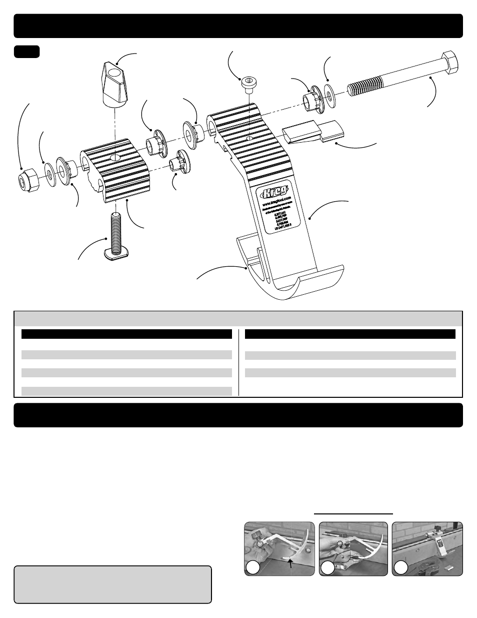
Assembly Instructions
About the Swing Stop
TM
Breakline
Hex Head Bolt
Brass Washer
Stop Base
T-Bolt
Swing Stop
TM
Arm
Breakline
Lens
Nyloc Nut
Plastic Stop
Bushing
Plastic Stop
Bushing
Plastic Support
Button
Plastic Stop
Bushing
Nylon Screw
Brass Washer
Won’t work loose
during use
Position on side of stop
base nearest blade.
Slides in T-Slot of
aluminum trak.
Anchors assembly to
aluminum trak.
Allows for
smooth operation.
Allows for
smooth operation.
Allows for
smooth operation.
Allows for
smooth operation.
Secures Swing Stop
TM
assembly
Tightens Swing Stop
TM
assembly in position
Allows precise adjustment
of Swing Stop
TM
Used to calibrate lens zero position
For use with
sacrifi cial fence
Fig. 6
Black T-Knob
Second, use a pliers to grip the
break-away portion of the Swing
Stop
TM
and simply “snap” that
piece off.
Third, fi le or sand off the rough
edge of the Swing Stop
TM
.
First, hold the Swing Stop
TM
fi rmly
in your hand. You may also use
a vice.
2.
3.
1.
The design of the Swing Stop
TM
will allow it to work with the addition of
a sacrifi cial board attached to the fence of our Miter Gauge. Sacrifi cial
boards afford a renewable surface to support the workpiece, resulting in
a smooth crosscut that minimizes tear-out.
The sacrifi cial board can be constructed from any material you choose.
The board must be 3/4” in thickness and may not exceed 2-5/8” in
height. Choose a length that best suits your application. Attach the board
to the Miter Gauge Fence with 1/4” diameter, 3/4” long bolts and nuts.
Drill 3-4 holes, with counter-bores, large enough to facilitate the bolt,
nut, and washer. Using this arrangement, the sacrifi cial board may be
moved along the fence independently of the measuring tape attached to
the fence. This eliminates the need to recalibrate the measuring system
each time you want to renew the backing surface.
The design of the Swing Stop
TM
makes it fully compatible with the
addition of a sacrifi cial board to the aluminum fence. A groove (breakline)
has been incorporated into the base of the Swing Stop
TM
Arm. This
breakline has been added to provide a simple means to shorten this
portion of the Swing Stop
TM
, for use with a sacrifi cial board. If you intend
on using a sacrifi cial board, remove the breakaway section of the stop,
as shown below. We suggest using a fi le or sandpaper to smooth the
rough edge of the Swing Stop
TM
after breaking it away.
Once the Swing Stop
TM
has been altered, it can only be used with a
sacrifi cial fence on the Miter Gauge. It will not work correctly if used
without a sacrifi cial fence.
WARNING!
Breakline
3 Simple Steps
KREG TOOL COMPANY
201 Campus Drive
Huxley, IA 50124
(*Make sure the Swing Stop
TM
Arm is on the same side of the Stop Base as the saw blade, drill bit or router bit.)
Swing Stop
TM
Parts Identifi cation
Name
Dimensions
Qty
Part#
Name
Dimensions
Qty
Part#
Swing Stop
TM
Arm
1
FT4261
Lens
1
FT4063
Nyloc Nut
5/16” - 24
1
FT4061
Brass Washer
5/16”
2
FT4137
Nylon Screw
10-32 x 1/4”
1
FT4064
Black T-Knob
1
DK1313
Hex Head Bolt
5/16” - 24 x 3 - 1/4”
1
FT4060
Stop Base
1
FT4262
T-Bolt
1/4” - 20 x 1-1/4”
1
FT4212
Plastic Stop Bushing
4
FT4257
Plastic Support Button
1
FT4258