K-Patents PR-33-S Troubleshooting Guide User Manual
Page 4
TROUBLESHOOTING GUIDE
FOR PR-33-S AND PR-33-AC
4 (10)
January 9, 2015
K-PATENTS OY
•
Postal Address: P.O.Box 77, FI-01511 Vantaa, Finland
•
Street Address: Elannontie 5, FI-01510 Vantaa, Finland
•
Tel. int.+358 207 291 570
Fax int.+358 207 291 577
•
•
www.kpatents.com
•
VAT No. FI03035575
•
Business ID 0303557-5
•
Registered in Helsinki
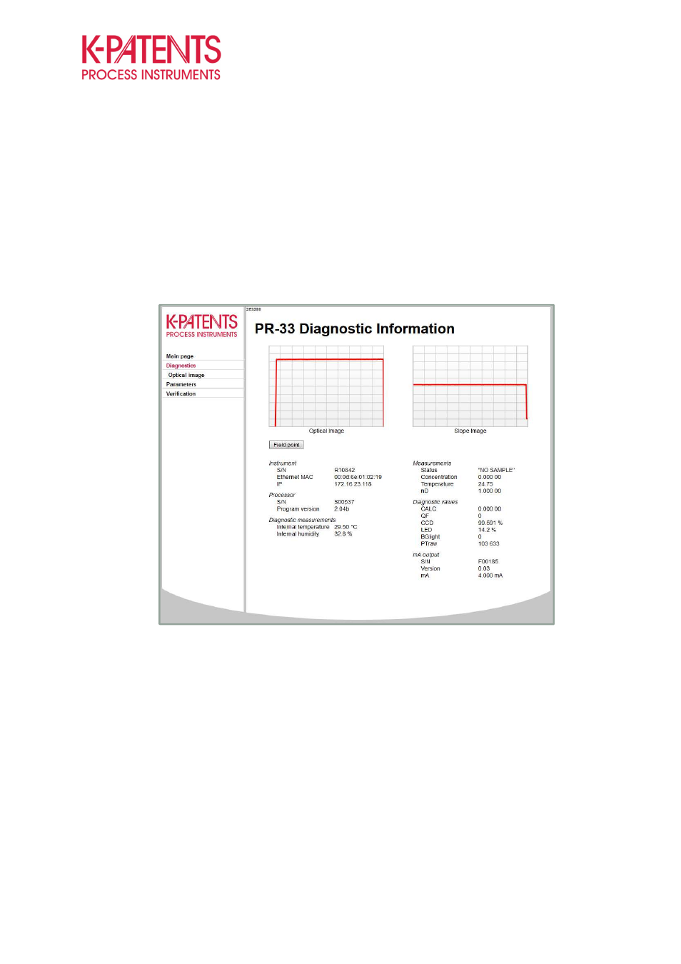
Interpreting the optical image and diagnostic values
The diagnostics tab on the instruments webpage contains most of the tools for troubleshooting. The optical
image can be used for inspecting the condition of the optics. The diagnostic values provide information about
the measurements, conditions inside the instrument and mA outputs. All these values can be used to
evaluate the stability of the measurement and condition of the electronics and optical components of the
instrument.
Figure 4
Diagnostics tab shows the current diagnostic values and optical image
Optical Image and Slope
The optical image can be described as a window to the process medium. However, it also gives information
about the condition of the prism and the optics. Scratches or coating layers on the prism can be identified
through the optical image. Altering shapes are formed with every change in the prism-process interface.
Generally, the instrument has two different optical images, i.e. the raw image and IDS scaled optical image.
The raw image is the real response signal from the fotocells of the CCD-element, which is also unique to
every instrument. Consequently, the IDS image was developed to unify the optical images making the
instrument more user friendly. The IDS image is created by mathematical scaling of the raw image to a
rectangular shape improving the measurement stability on high and low refractive index (RI) ranges.