Installation, Continued, Installing optional blower accessory ga3450ta – Desa FDCFTP User Manual
Page 13
www.desatech.com
111244-01F
13
INSTALLATION
Continued
Figure 16 - Removing Top Louver and
Opening Bottom Louver
O
F
F
P
ILO
T
O
N
H
I
L
O
Top
Louver
Bottom Louver
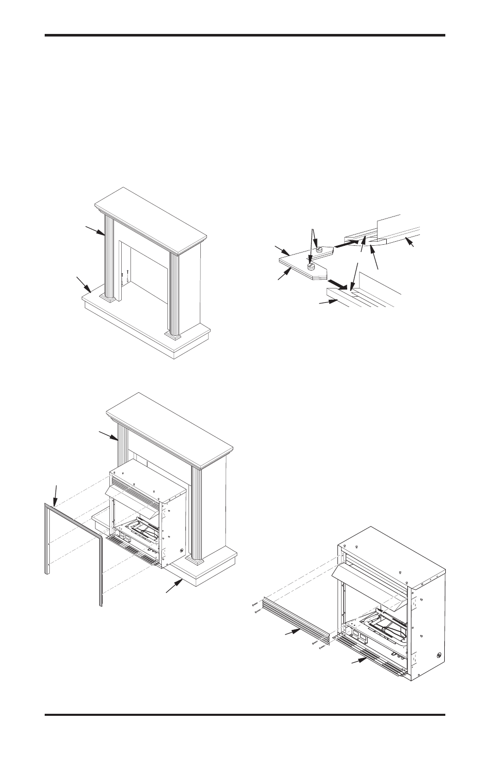
11. Place metal trim on shoulder screws located
on the side and top of the fireplace (see Assem-
bling Perimeter Trim). Firmly snap trim over
shoulder screws. Align fireplace in mantel
assembly so the trim overlaps mantel evenly
on all three sides.
12. Lower bottom louver door. Use 3" wood screws
provided with mantel accessory to attach fire-
place to base (see mantel instruction sheet).
O
F
F
P
ILO
T
O
N
H
I
L
O
Assembling Perimeter Trim (Perimeter
trim shipped with mantel)
1. Remove packaging from three remaining
pieces of trim.
2. Locate two adjusting plates with set screws,
and two shims in the hardware packet.
Figure 15 - Assembling Brass Trim
Side Brass
Trim
Top Brass
Trim
Mitered Edge
Shim
Set Screws
Adjusting
Plate
Slot
3. Align shim under adjusting plate as shown in
Figure 15.
4. Slide one end of adjusting plate/shim in slot on
mitered edge of top brass trim (see Figure 15).
5. Slide other end of adjusting plate/shim in slot
on mitered edge of side perimeter trim (see
Figure 15).
6. While firmly holding edges of perimeter trim
together, tighten both set screws on the adjust-
ing plate with slotted screwdriver.
7. Repeat steps 1 through 6 for other corner.
8. Set perimeter trim assembly aside for later
installation.
Figure 13 - Installing Cabinet Mantel onto
Hearth Base
Figure 14 - Installing Fireplace into
Mantel Assembly
Cabinet
Mantel
Hearth
Base
Cabinet
Mantel
Assembled
Trim
Hearth Base
INSTALLING OPTIONAL BLOWER
ACCESSORY GA3450TA
Removing Upper Louver
To install the blower accessory, you must first
remove the upper louver.
1. Lift screen off fireplace and remove log set if
installed.
2. Remove 4 screws from upper louver (see
Figure 16). Save these screws.
3. Pull upper louver straight out from the cabinet. Be
careful not to scratch the paint. Set louver aside.
4. Open lower louver door by swinging door
down (see Figure 16).