2-3 header pin definition, Cdin, Cd audio-in headers – Jetway Computer NMF91-G41 User Manual
Page 16
12
second drive to Slave mode by setting its jumpers accordingly. Please refer to
the documentation of your hard disk for the jumper settings.
• Two hard disks can be connected to each connector. The first HDD is referred
to as the “Master” and the second HDD is referred to as the “Slave”.
• For performance issues, we strongly suggest you don’t install a CD-ROM or
DVD-ROM drive on the same IDE channel as a hard disk. Otherwise, the system
performance on this channel may drop.
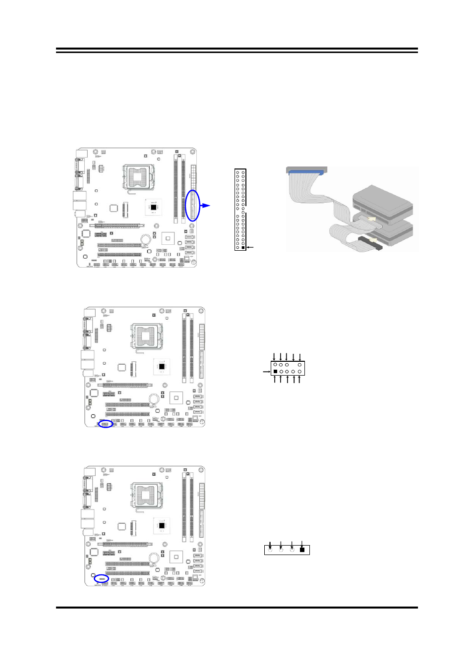
IDE Connector
Pin 1
IDE1
2-2-3 Header Pin Definition
(1) Line-Out/MIC Header for Front Panel (9-pin): FP_AUDIO
This header is connected to Front Panel Line-out, MIC connector with cable.
Line-Out, MIC Headers
AUDIO
Pin 1
Li
ne
out
2
-L
Li
ne
out
2
-R
S
e
n
s
e-
FB
Au
di
o-G
ND
LI
N
E
2
-JD
A
u
d
io-
JD
2
9
10
KE
Y
MIC
2
-L
MI
C2
-J
D
MIC
2
-R
(2) CD AUDIO-In Headers (4-pin): CDIN
CDIN is the connector for CD-Audio Input signal. Please connect it to CD-ROM
CD-Audio output connector.
CD Audio-In Headers
CDIN
4
1
GND
CD-R
CD-L
GND