3 layout diagram – Jetway Computer NF3D User Manual
Page 8
3
4* Serial port header
(COM1 supports RS422/RS485 function)
2* 9-pin USB 2.0 header (Expansible to 4* USB 2.0 ports)
1* GPIO header
1* SM_BUS header
1* PS2KBMS header
1* Front panel header
1* LAN LED activity header(JP9)
1* LVDS header
1-3
Layout Diagram
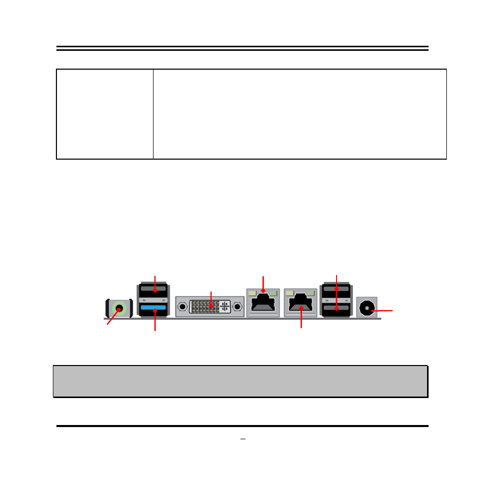
Rear IO Panel Diagram:
*Notice: Please connect compatible power supply to the power connector. The voltage of power
connector should not be lower than 9V or higher than 24V, otherwise it may do harm to the board &
other devices!
9V~24V DC
Power-in
Connector
Line-Out Port
USB 2.0 Ports
DVI-I Port
USB 3.0 Port
USB 2.0 Port
LAN1
RJ-45 LAN Port
LAN2
RJ-45 LAN Port
This manual is related to the following products: