Assembly instruction, Pt4000 – ikan PT4000 User Manual
Page 4
3903 Stoney Brook Dr. Houston TX 77063 | +1.713.272.8822 | www.ikancorp.com | [email protected] | © 2009 ikan Corporation. All right reserved.
ASSEMBLY INSTRUCTION
5
6
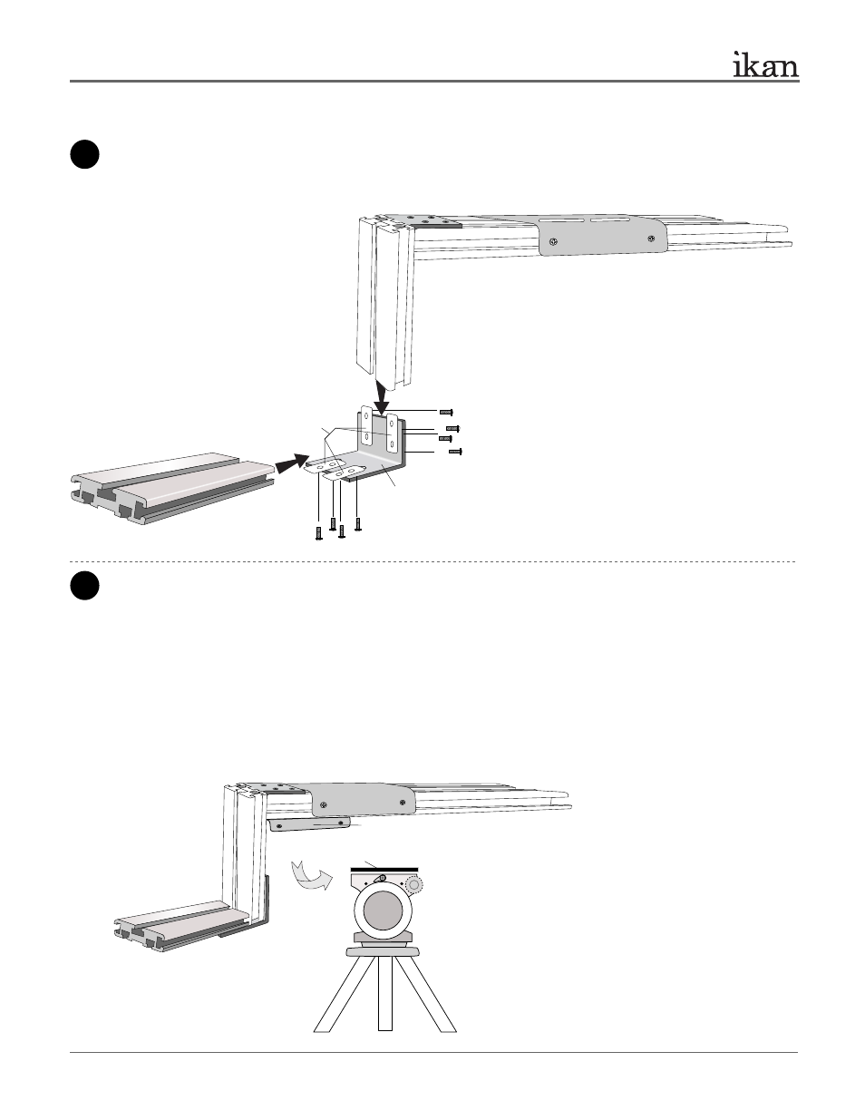
Attach another L-Bracket (Part-J) to the assembled parts. Make sure to arrange the long section of Part J as shown in the
illustration, otherwise there will not be adequate room to place the monitor. You will use 4 x Long Phillips head screws
(Part-G) and 2 x T-plates (Part-C) to attach it. Then, you will use 4 x Long Phillips head screws (Part-G) and 2 x T-plates
(Part-C) to attach the 15” T-slot (Part-O). Make sure to evenly tighten all screws in the assembly.
PT4000
20” TELEPROMPTER
Part-O
Part-G
Part-G
Part-C
Part-J
ikancorp.com
Attach your tripod skid plate to Part-N.
For those who use a tripod that is rear loading (ie: your tripod skid plate slides into the tripod head from the rear), we have provided an
optional piece , Part-N, will allow for more convenient attaching and detaching of the PT4000 Teleprompter on your tripod.
> Loosen the screws and slide out the Metal Bracket
through the channels
> Install 2 x Part-A & Part-E or 2 x Part-B & Part-F
> Slide in the Metal Bracket through the single channel
of the bottom of the Part-P
> Attach your tripod skid plate to the remaining Part-N (8” T-Slot)
and secure them on your tripod head
> Attach the assembled teleprompter to your tripod
your
tripod
Part-N (Metal Bracket)
Part-N (8” T-Slot)
ikancorp.com
Important Note: Your tripod or pedestal should be a heavy-duty
grade. The PT4000 is a heavy studio teleprompter and many
tripods may not be able to hold the weight of it. Be sure that your
tripod and head can handle it.
3 of 10