5 scale drawing, 6 electrical connection, 1 bus termination – ifm electronic JN2301 User Manual
Page 6
Inclination sensor JN
6
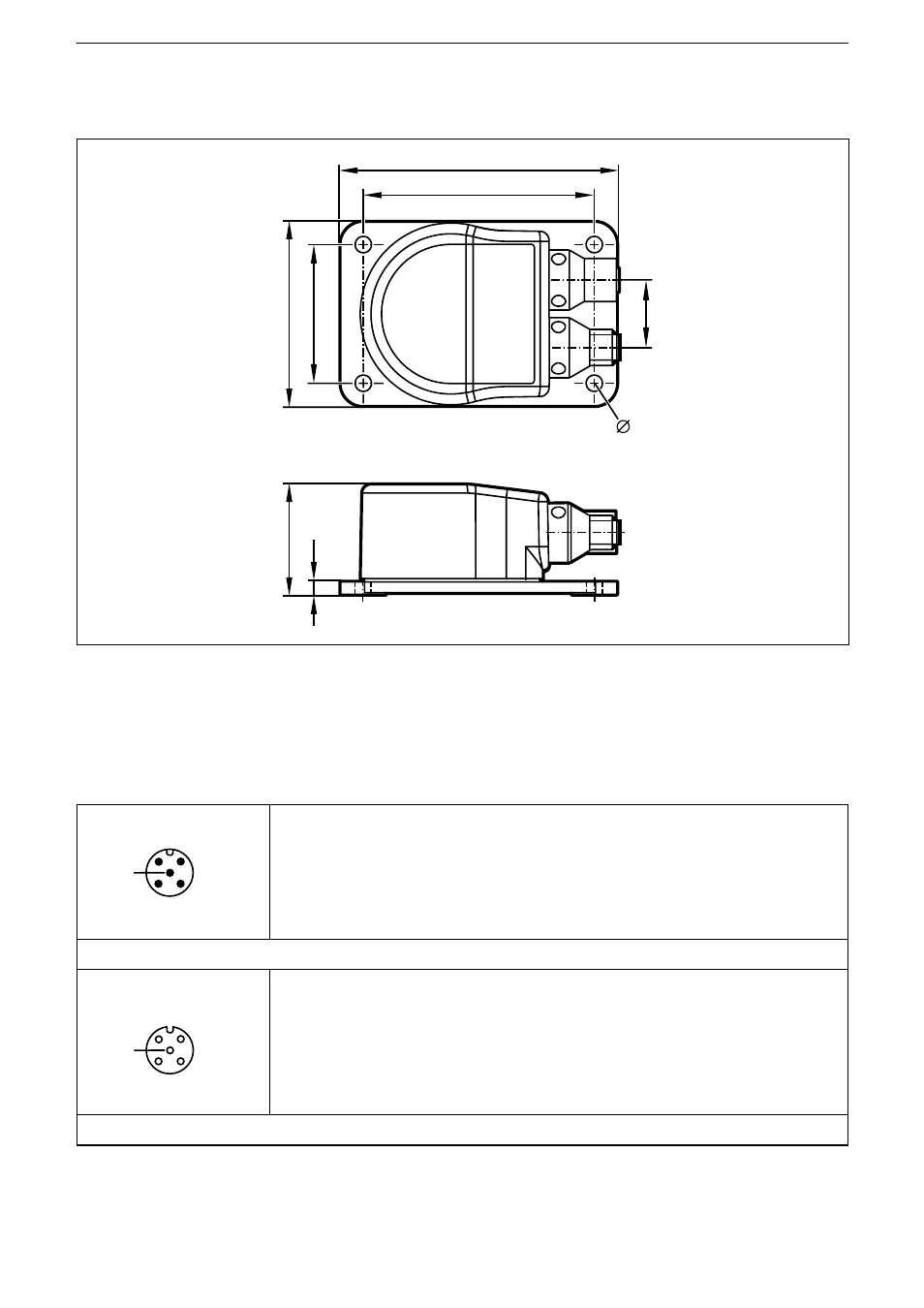
5 Scale drawing
36
4,
5
90
75
22
45
60
5,3
6 Electrical connection
The inclination sensors are fitted with two round 5-pole M12 connectors (A-coded)�
The pin configuration is as illustrated�
4
2
1
3
5
1: CAN_SHLD CAN shield
2: CAN_V+ Supply voltage 24 V DC (+UB)
3: CAN_GND Ground
4: CAN_H High bus cable
5: CAN_L Low bus cable
M12 connector CAN-In
3
1
2
4
5
1: CAN_SHLD CAN shield
2: CAN_V+ Supply voltage 24 V DC (+UB)
3: CAN_GND Ground
4: CAN_H High bus cable
5: CAN_L Low bus cable
M12 socket CAN-Out
6.1 Bus termination
The inclination sensors have an internal 120 Ohm terminating resistor that can be
assigned (index 0x2045)�