2 upload/download (0x3000), 3 measured data (0xa000 – 0xa011), 9 angle definition (0x2044) – ifm electronic JN2301 User Manual
Page 13: 1 perpendicular angle (0x2044 = 0)
UK
Inclination sensor JN
13
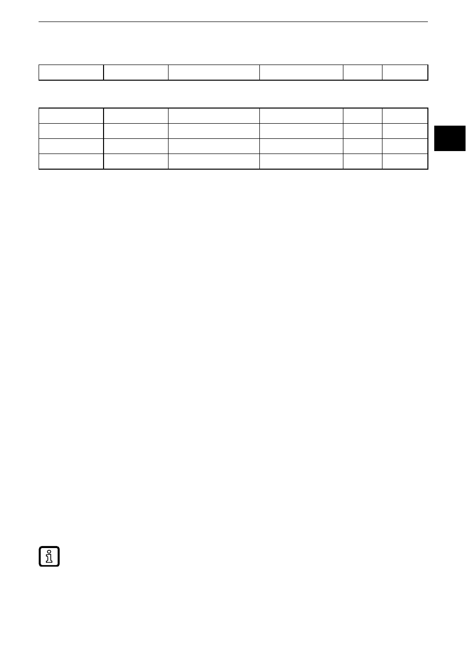
8.2.2 Upload/download (0x3000)
0x3000
ASCII
Programming key
R/W
8.2.3 Measured data (0xA000 – 0xA011)
0xA000
INTEGER16
Longitudinal X axis
°
R
0xA001
INTEGER16
Lateral Y axis
°
R
0xA010
INTEGER32
Longitudinal X axis
°
R
0XA011
INTEGER32
Lateral Y axis
°
R
9 Angle definition (0x2044)
To be able to adapt the inclination sensor to the different applications as easily
as possible, the measured inclination information is converted into different angle
indications� The requested angle indication is set by selecting the respective
option�
With this angle definition a sensor coordinate system is used which is defined as
follows:
– The mounting plane corresponds to the XY plane�
– The z axis is perpendicular to the mounting plane (according to the right-
hand rule)�
– The X axis is represented by an edge of the mounting plate which shows in
direction of the printed X arrow�
– The Y axis is then perpendicular to the plane spanned by the Z and X axes�
9.1 Perpendicular angle (0x2044 = 0)
Using the indication of the two perpendicular angles the inclination of the sensor
coordinate system towards the direction of gravitation is described�
The first provided value corresponds to a rotation about the Y axis of the sensor
and is called "longitudinal inclination value"�
The value corresponds to the angle [°] which the gravitation vector spans with the
YZ plane�
The first provided value corresponds to a rotation about the X axis of the sensor
and is called "lateral inclination value"� The value corresponds to the angle [°]
between the gravitation vector and the XZ plane of the sensor�
In the case of an inclination in a plane (rotation of an axis with the second axis remaining
perpendicular) the perpendicular angle and gimbal angle are always identical�