Herrmidifier Herrtronic AD User Manual
Page 7
Herrtronic AD Series Installation, Operation and Service Manual
WARNING!
Do not mount any controls inside the unit or tap
power from any location in the unit, except as
stated in these instructions. Do not place
objects near the cabinet. Do not attach to dry
wall without studs.
WARNING!
Do not mount any controls inside the unit or tap
power from any location in the unit, except as
stated in these instructions. Do not place
objects near the cabinet. Do not attach to dry
wall without studs.
SECTION III INSTALLATION INSTRUCTIONS
Mounting
The cabinet is designed to safely contain the working
parts of the Herrtronic AD Series and dissipate heat to
protect the electronics. Herrtronic AD Series electronic
steam humidifiers, room distribution unit, steam pipes,
and any accessories should be located in a manner to
facilitate routine inspection and any necessary mainte-
nance. The unit should not be located above (such
as false ceilings) or around valuable property where
an equipment malfunction could cause damage.
Correct positioning of the Herrtronic AD Series is
important to allow for proper operation and easy
maintenance. Minimum clearances around the cabinet
should be maintained as shown:
CLEARANCES
UNIT
SERIES
ADM
5-30#
ADS
10-100#
Left
Right
Top
Bottom
2”
15”
12”
10”
2”
15”
12”
10”
Allowable Operating Conditions
Ambient Temperature: 40
°F (4°C) to 120°F (50°C)
Ambient Relative Humidity: 0% to 90% (non-condensing)
Line Voltage: -15% to +10% of Nominal
Frequency: 50/60 HZ.
Supply Water Pressure: 20 psi- I 00 psi
Supply Water Temperature: 40
°F- I 00°F
Supply Water Conductivity: 70- 1 000 micromho
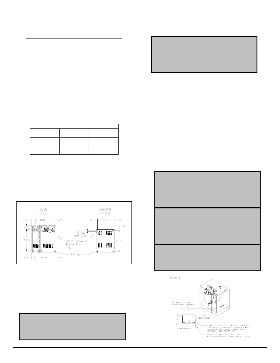
Four lag bolts, (2) 5/16" and (2) 1/4", are supplied with
the AD Series which is designed to be secured to a wall.
Install the top two lag bolts (5/16") according to the
dimensions in Figure 3. Hang the unit on the wall, and
then install the bottom two lag bolts (1/4") and secure all
four bolts. Be sure the unit is mounted directly to the wall
- to wood studs at least 2" thick (or equivalent.)
Plumbing
To make the necessary connections for water fill,
cylinder drain and cabinet drain, the following steps are
required: (refer to Figure 3 for locations)
1. Install an external shutoff valve between the water
supply and the humidifier for ease in servicing of the
unit.
2. Connect water supply to 1/2" compression fitting on
the bottom of the cabinet using copper, PVC, or plastic
tubing.
3. A 3/4" hose barb adapter extends from the side of the
drain reservoir on the bottom of the unit. This reservoir
collects both the cylinder and the cabinet drains in one
location. A 3/4" I.D. vinyl tube is included to be
connected to the drain reservoir and the drain line. The
drain line must be a minimum I" I.D. PVC or copper line.
NOTE
Inlet water pressure must be in the range of 20-
100 psig. Consult the factory if you are outside
of this range. Softened water may be used and
requires that the low drain threshold be
“adjusted.”
NOTE
To mount the Room Distribution Unit refer to the
supplemental RDU Installation Instructions.
WARNING!
Do not use plastic drain line unless “Drain
Tempering” is enabled. See page 11 for drain
tempering instructions.