Henry Engineering DigiStor II User Manual
Page 3
connected to Common (P1-1). Recording will terminate when this closure is released. This mode is applicable
when only one message needs to be recorded via remote control, e.g, "network news delay".
4.2.4 PLAYBACK VIA REMOTE CONTROL: To play any message, provide a momentary contact closure
between the desired Message # and Common. For example, to play Message #5, provide a contact closure
between P1-6 and P1-1. NOTE: Some modes of operation require a maintained closure; see section 5.0 for
details about the various playback modes available. During playback, the Message # LED will remain ON. To stop
message playback, provide a momentary contact closure between P1-10 (Stop input) and P1-1 (Common).
4.3 USING DIGISTOR II ON A TELEPHONE LINE: DigiStor II can be used to automatically answer a phone line
and play a message(s) to callers. This mode requires the use of the automatic tele-coupler, included. The tele-
coupler should be installed as follows:
1. Mate the tele-coupler to the 12-position connector (used for Remote Control Connector #1). The six male pins
on the tele-coupler circuit board should be plugged into terminals 1, 2, 3, 10, 11, and 12 of the 12-position
connector. Unscrew the locking screws for these terminals on the connector, slide the male pins into the connector,
then re-tighten the screws. BE SURE that Pin #1 on the tele-coupler is mated to position #1 on the connector!
Now plug the 12-position terminal block into Connector #1 (P1) on the DigiStor II.
2. Plug the RCA plug that is attached to the tele-coupler into the LINE OUTPUT (RCA) jack on the DigiStor II.
Set the LINE OUTPUT level control fully CW.
3. Connect a standard phone line to the tele-coupler via the modular phone jack.
4. Set the CONFIG switches as follows:
#1, #2: As needed for single-play or repeat play per call. (#1 & #2 UP=Message plays once per call.)
#3, #4, #5, #6, #7: All switches UP.
WARNING! Be sure your phone line is protected against high-voltage 'spikes' and lightning strikes! Use
a surge suppression device to prevent voltage spikes from getting into DigiStor II! High-voltage 'spikes' and
lightning will cause permanent damage to DigiStor II. This damage is NOT covered under your warranty!
Record a message into the DigiStor II using local control. (See Section 4.1.1) BE SURE to record the message
using MESSAGE #1. When the phone line is called, DigiStor II will answer the line a begin playback of the
message. If the caller hangs up during the message, DigiStor II will stop playback, reset the line, and wait for the
next call.
Another possible mode of phone line operation is "rotation play", where DigiStor II plays a different message to
each caller, "in rotation". The first caller would hear Message #1, the next caller would hear Message #2, and so
on. To use this feature, record several messages as usual. Set CONFIG switches as described above, EXCEPT
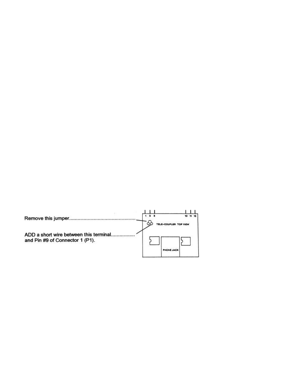
set CONFIG SWITCH #7 DOWN. The tele-coupler module will need to be modified as follows, see drawing below:
4.4 USING DIGISTOR II FOR MESSAGE-ON-HOLD To use DigiStor II for message-on-hold, record message #1
as usual. Set CONFIG switches #1 & 2 DN, and provide a maintained closure between P1 pins 1 and 2 to start
playback. Do NOT use the tele-coupler. Feed audio from DigiStor II to the "Music-On-Hold" input of phone system.
5.0 SETTING THE CONFIG SWITCHES (NOTE: CONFIG switches affect playback via remote control only.)
DigiStor II has numerous modes of operation that can be programmed with the 8 CONFIG switches. (The switches
are numbered from left to right, 1 through 8.) When DigiStor II is shipped, all CONFIG switches are UP, setting the
unit for normal "default" operation. NOTE: The CONFIG switches are "read" by the system only during power-up.
Changing any CONFIG switches while the system is powered up will have no effect unless the system is shut
down, then powered-up again. (UP=switch is up; DN=switch is down.)
REPEAT MODES: Switches #1 and #2 select the number of times a message plays when triggered, as follows:
#1
#2
UP
UP
Play message 1 time
UP
DN
Play message 2 times
DN
UP
Play message 3 times
DN
DN
Play message 4 times
RECORD MODE:
Switch #3 selects the Record mode.