Installation 5 6 – Guralp Systems CMG-5TD Installation User Manual
Page 2
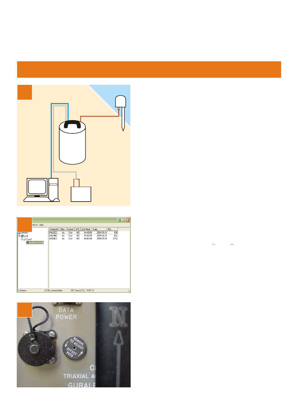
4
RS232
GPS
Power
supply
+
–
PC
CMG-5TD
Installation
5
6
Remove the screw-on cap protecting the offset
adjusters. With a small screwdriver, adjust each offset
until the corresponding output in the waveview window
is close to zero. Zoom in as necessary.
Replace the pressure cap. The sensor is now ready for
use.
Please refer to the full manual for detailed
instructions on usage, calibration and
troubleshooting.
MSH-050-0003-C : Page 2 of 2
Connect the various components together:
•Connect the brown cable from the GPS receiver to
the GPS connector on the sensor;
•Connect the 9-pin ‘D’ connector on the blue cable to
your PC’s serial (COM) connector;
•Connect the free, stripped end of the grey cable to
the power supply. Connect the black wire to the
negative (–) terminal and the red wire to the positive
(+) terminal;
•The blue and grey cables are joined together at a 10-
pin mil-spec socket. Attach this to the DATA
connector on the sensor. Do this step last.
Start the PC and run Güralp Systems’ Scream! software.
If you have not run Scream! before, the Setup window
will open. Otherwise, choose File → Setup... from the
main menu and view the Com Ports tab.
Set the Baud Rate to 38,400 and click OK. Data
streams should start appearing in the main window.
Highlight the Z, N and E streams by control-clicking
them and press Enter to open a waveview window.