Important – Gullco KR-200-L User Manual
Page 21
T-1
IMPORTANT
READ THIS BEFORE OPERATING THE “GSP-1000” CONTROL
Read and understand the operation manual before operating or performing service of this
equipment. Become familiar with the machines operation, applications and limitations. Keep the
operation manual in a clean and readily available location.
The motor control must not be continually started and stopped by the removal and reapplying of
power to the control. Turning the power off to the control will not provide regenerative braking and
continued use will damage the control.
Allow ten (10) seconds after the removal of power before reapplying the power to the "GSP" control.
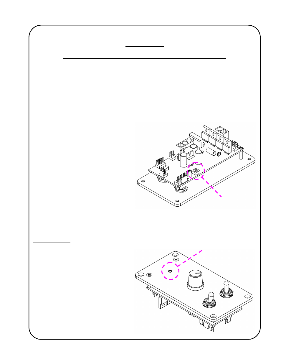
Current Overload Setting (VR2)
The “Current Limit” (motor overload
protection) on this product is typically
factory preset to 70% (1 to 2 o’clock
position) unless specifically requested at
time of order. If a specific application
requires that this be changed (to prevent
damage to drive mechanism), use the
circuit board mounted variable
potentiometer, VR2 (located on the
underside of the control circuit board.
When adjusted, this potentiometer will set
the amount of current allowed to pass
through the motor control before it will shut-
down. It is recommended that the setting
be made excessively low, and gradually increased until the desired protection is achieved. Always
perform this procedure under worse case allowable conditions, I.e. vertically up instead of vertically
down.
Diagnostic LED
The microprocessor based “GSP-1000”
control has built in safety logic that reduces
the risk of injury, damage and faulty
operation. The “GSP-1000” control flashes
its Diagnostic LED in preset sequences to
indicate a potential problem.
The diagnostic LED is visible by removing
the round head Philips screw from the
faceplate.
The table on the following page provides
information regarding the Diagnostic LED.
VR2
Remove this screw
to view the
Diagnostic LED