Groth 1721B User Manual
Page 8
Page 8 of 18
SPRING LOADED PALLET ASSEMBLY
1. Remove cap and hex jam nut.
2. Carefully measure and record the distance from the top of the adjustment screw to the top of the spring chamber. (Dimension
"D" - See Figure 3).
3. Relieve all spring compression by turning the adjustment screw counterclockwise.
4. Loosen and remove all hex nuts and washers.
5. Lift the spring chamber from the body.
6. Remove the upper spring button and spring. Remove the pallet assembly by firmly grasping the stem and lifting up. If more than
one valve is being disassembled, tag the assemblies as they are removed from the valves.
7. Carefully inspect all guides for corrosion, damage or product build up. Also inspect the adjustment screw and spring chamber
(#2) for thread damage or galling. Check the metal seating surfaces for pitting or build up. It is recommended that all soft goods
including diaphragms, O-Ring and spring chamber gasket be replaced.
NOTE: If the seat is damaged it must be lapped using a ground flat metal disc and a fine grit emery cloth attached to the disc.
Wipe seating surface clean before proceeding.
8. Prior to final assembly, verify that the pallet and spring are back in their proper location. Assemble in reverse order. Make sure
that pallet assembly is flat on the seat and that the stem is not cocked when the spring chamber is installed. Oil, grease or other
lubricant are not required on guides or other metal surfaces of valves, and can hinder free movement. Lubricate the adjustment
screw threads with an appropriate thread lubricant. If the valve is in high temperature service or stainless steel external
fasteners are used, apply an anti-seize compound such as moly-disulfide to all threaded components. Tighten all hex nuts
firmly.
9. If the spring is being re-used, compress it by turning the adjustment screw clockwise until the distance from the top of the
adjustment screw to the top of spring chamber matches the distance "D" measured in Step 2; proceed to Step 11.
10. If the spring is replaced, use only original springs supplied by Groth Corporation and follow the Procedure illustrated below:
11. Replace and tighten hex jam nut firmly. Replace cap.
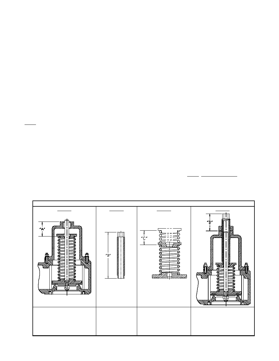
FIGURE 3: SPRING SETTING PROCEDURE
STEP 1
STEP 2
STEP 3
STEP 4
After removing the adjustment
screw (#4) measure the
distance from top of spring
chamber to counter bore on
spring button for the dimension
"A".
Measure overall
length of
adjustment screw
for dimension "B".
This is the required
compression to achieve
the design set pressure.
Consult factory for
determination of “C”
dimension.
Use the following calculation to
obtain the "D" dimension.
Compress the spring by turning
the adjustment screw clockwise
accordingly.
D = B-A-C