Groth 8860 User Manual
Page 5
IOM -8860
Page 5 of 13
13650 N. Promenade Blvd. * Stafford, TX 77477
Office: (281) – 295-6800 * (800) – 354-7684 * Fax: (281) – 295-6999 * www.grothcorp.com
Exceeding the spring upper limit may compress the spring to its solid height, and prevent the
regulator from opening. Setting it below the lower limit may prevent the regulator from closing
fully at the required pressure.
PROCESS PIPING IS TO BE CLEAN AND FREE OF WELD SLAG. WELD SLAG OR OTHER
DEBRIS COULD BLOCK THE SENSE LINE OR DAMAGE THE REGULATOR SEATING SURFACE.
DO NOT LIFT THE BACK PRESSURE REGULATOR FROM THE ADJUSTMENT SCREW. IF
LIFTED FROM THIS LOCATION, THE ADJUSTMENT SCREW MAY BE PERMANENTLY
DAMAGED.
USING AN IMPROPER PRESSURE SENSING LINE CAN RESULT IN LIMITED OR NO
FUNCTIONALITY OF THE REGULATOR. RECOMMENDED SIZE FOR THE PRESSURE SENSING
LINE IS AT LEAST .31”. THIS LINE MUST REMAIN FREE OF DEBRIS AND ANY TYPE OF
OBSTRUCTION.
IV. INSPECTION AND INSTALLATION
The regulator is packaged and supported to prevent damage or contamination during shipment. The
regulator shall also be protected during subsequent handling and storage. Always keep all ports
plugged to prevent intrusion of foreign materials. Before installation, inspect the unit visually. If there
are indications of physical damage or internal contamination, the regulator must be disassembled,
cleaned and inspected before installation. If factory set, the spring adjustment cap must be secure.
Report any shipping damage to carrier.
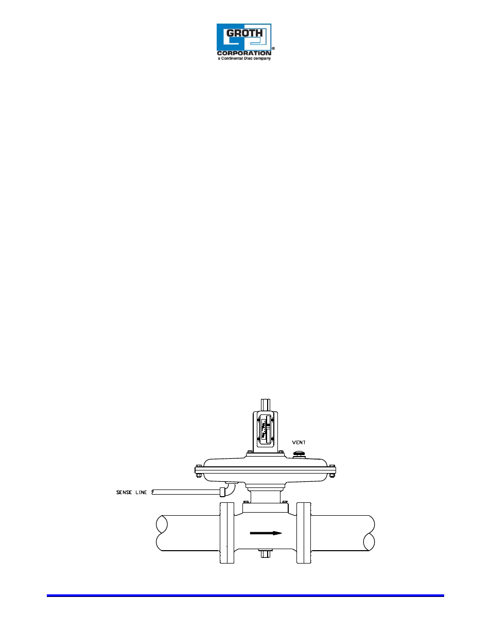
The regulator must be installed in a horizontal line as shown in Figure 1. Use the actuator housing or
valve body to lift and support the regulator at installation.
1. Aluminum bodies should be connected with flat-faced 150# ANSI flanges using a full-faced gasket.
Mating flanges should be flat within .020", clean, free of scratches, corrosion and tool marks.
2. Steel bodies should be connected with raised-faced 150# ANSI flanges using a full-faced or ring
gasket. Mating flanges should be flat within .020", clean, free of scratches, corrosion and tool
marks.
3. Each valve is leak tested at the factory as part of our standard inspection procedures.
4. Inspect the gasket; make sure that the material is suitable for the service. Gasket dimensions are
listed in Table 1. Full gaskets must be used with flat face flanges. Either full or ring gaskets may be
used with raised face flanges.
Figure 1: Regulator