Pilot valve design and function – Groth 1401E User Manual
Page 3
2
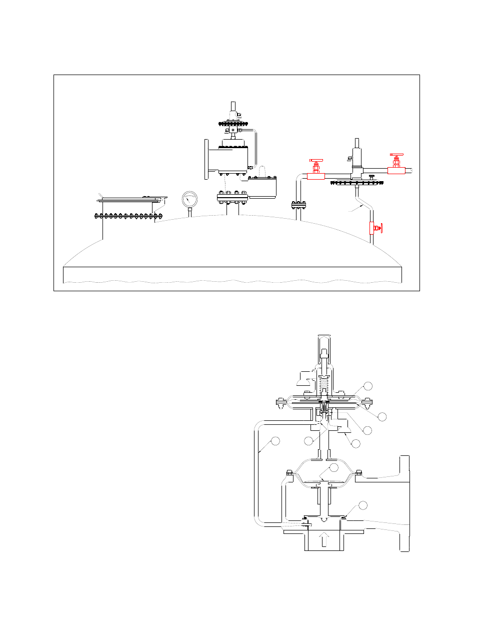
Figure 1: Tank Installation - Safety Equipment
GAUGE
EMERGENCY RELIEF VALVE
GROTH MODEL 2400
PRESSURE/VACUUM
RELIEF VALVE
GROTH MODEL 1420
BLANKET GAS REGULATOR
GROTH MODEL 3000
BLANKET
GAS
SUPPLY
SENSE LINE
PILOT OPERATED
PILOT VALVE DESIGN AND
FUNCTION
Note that throughout this manual, numbers in [ ] after
the part descriptions are item numbers which refer to
the drawings and bill of materials.
The function of the pilot valve is to control pressure
to the actuator of a pressure relief valve. The
pressure relief valve is designed so the effective area
of the actuator (1) is significantly larger than the
valve seat area (2). Therefore when tank pressure is
applied to the actuator, the closing force is greater
than the opening force so tight shut-off is achieved.
The pilot seat is held closed by the adjustable set
pressure spring. Tank pressure is conveyed to the
pilot valve by the pilot pickup tube (3), and directly
applied to the booster diaphragm (4).
Simultaneously pressure is applied through an
adjustable orifice (6) to the space between the
diaphragms and to the pressure relief valve actuator,
closing the relief valve. The net force attempting to
lift the pilot spool is the tank pressure acting on the
effective area of the sense (smaller) diaphragm (5).
Fig. 2 Shut - Off Condition
2
1
8
5
3
7
6
4