Operation, Installation, Main power wiring – Greenheck Universal Control - MS-1P (476374) User Manual
Page 2: Low voltage wiring, Overload adjustment, Operation modes, Led status indicators, Warning, Mounting
2
Motor Starter Single Phase
Main Power Wiring
Wire main power input and output to the appropriate
12AWG wire leads utilizing properly sized wire nuts. Use
only copper conductors rated at least 60°C. Maintain
proper clearances and verify that no possibility of an
electrical short exists between the power conductors or
enclosure. Ensure that wires are not under stress and all
insulation is intact.
Low Voltage Wiring
Automation system control wiring should be run in
a separate conduit. The control terminals accept
26~14AWG wire torqued to 3.5 in-lb.
1Ø AC Input 50/60 Hz
L1
L2
T1
T2
M
Voltage Input
Auto Run
Fault
Output
Status
Output
Dry Input
Auto Run
Normally Open
Input
12-120VAC/DC
Input
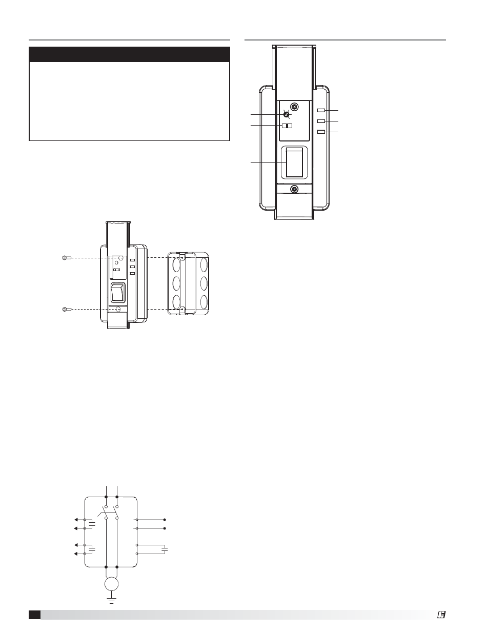
1. Overload Adjustment
2. Operation Mode Selector
3. Main Power / Disconnect
4. PWR Power Status LED
5. RUN Run Status LED
6. FLT Fault / Overload LED
HAND RESE
T
AU
TO
PWR
RUN
FLT
1
2
3
4
5
6
Overload Adjustment
Confirm nameplate Full Load Amperage (FLA) to
ensure proper overload protection. Using a flathead
screwdriver, turn the adjustment dial to the desired
amperage setting. The starter is not rated to protect
loads exceeding 16 amps.
Operation Modes
RESET: To reset the starter to normal operation
following a Fault condition, slide the 3-position
switch to RESET and hold for a minimum of 5
seconds (after 180 second cool down period has
elapsed). Once starter has been reset, return switch
to the desired mode.
MANUAL (HAND MODE): In Manual or HAND mode,
the MS-1P will function as a motor disconnect or
“manual motor starter.” Select the ON (
ƫ) position on
the main power switch to engage motor.
AUTOMATIC (AUTO MODE): When utilizing the
starter in the AUTO mode, a signal sent via the
terminal inputs (located on rear of unit) determine
motor operation (ON or OFF).
LED Status Indicators
POWER
(PWR): Illuminates when voltage is applied
to the input terminals and main power switch is in
the ON (
ƫ) position.
RUN: Under a RUN condition, the RUN LED will
remain illuminated if the MS-1P senses current
providing status. The LED will flash when the unit
does not sense current.
FAULT (FLT) - Overload Trip: The MS-1P indicates a
fault condition by flashing the red FAULT LED which
will remain constant in the event of a fault trip. The
LED will also flash if a RESET attempt is made during
the 180 second overload cool down period.
Operation
WARNING
• Do not locate starter in an environment subject to
flammable gases, dusts or materials. Contact arcing
can induce explosion or fire.
• Install starter in UL Type 1 (NEMA-1) appropriate
locations only. Safe mounting requires a dry,
protected environment.
• Do not allow any metal shavings or debris from
installation to enter enclosure.
Installation
Mounting
Mount the starter on a minimum 14 cu-in single gang
junction box. To access mounting holes, slide upper and
lower covers to the open position. (See Figure 1)
Using provided mounting screws (6-32 x 7/8-inch),
attach starter housing to junction box (once appropriate
wiring has been completed).
Figure 1
®