Mullion installation, Static fire damper installation, Detail g-g – Greenheck Support Mullions for use in Oversize Openings (462105) User Manual
Page 3: Detail f-f detail d-d, Detail e-e, 20 x, In. long flat head steel bolts and, In. x 1, In. (6mm) dia. bolts, Inches (31mm)
6
F
3
/
16
in. dia.
(12 holes)
1
3
/
4
1
1
/
2
3
/
4
1
1
/
2
1
/
2
Horizontal Mullion Channel
End View
Side View
Top View
E
H
3
1
/
4
1
13
/
16
One or two piece
Side View
End View
End Plate
Center Channel
Weld
1
3
/
8
3
/
16
Use
3
/
16
dia. steel blind
rivets at installation
Weld
Assembled View
1
6
F
3
/
16
in. dia.
(12 holes)
1
3
/
4
1
1
/
2
3
/
4
1
1
/
2
1
/
2
Horizontal Mullion Channel
End View
Side View
Top View
E
H
3
1
/
4
1
13
/
16
One or two piece
Side View
End View
End Plate
Center Channel
Weld
1
3
/
8
3
/
16
Use
3
/
16
dia. steel blind
rivets at installation
Weld
Assembled View
1
6
F
3
/
16
in. dia.
(12 holes)
1
3
/
4
1
1
/
2
3
/
4
1
1
/
2
1
/
2
Horizontal Mullion Channel
End View
Side View
Top View
E
H
3
1
/
4
1
13
/
16
One or two piece
Side View
End View
End Plate
Center Channel
Weld
1
3
/
8
3
/
16
Use
3
/
16
dia. steel blind
rivets at installation
Weld
Assembled View
1
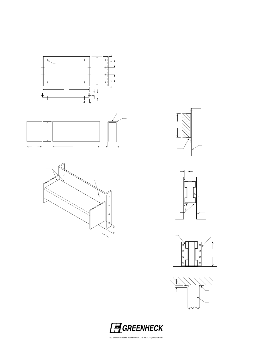
Mullion Installation
Before the static fire dampers are installed into the wall
the mullions must first be anchored into the wall. The fire
dampers may then be installed into the mullion assembly.
To correctly attach the mullions to the wall follow these
steps:
1. Anchor wall mullion caps to wall using
1
/
4
-20 x
5
/
16
in.
long flat head steel bolts and
3
/
8
in. (9.5mm) diameter by 1
in. (25mm) long concrete expansion anchors (Hilti). If steel
lintels are present, use two 1 in. (25mm) long welds on
each side of mullion caps.
Note: End caps must be inserted into the ends of the
mullions before they are anchored to the wall.
2. Anchor horizontal mullion caps to vertical mullion
caps with
3
/
16
in. (4.7mm) diameter steel blind rivets in 12
places.
NOTE: If the center channel is to be made from two pieces,
weld them together with an
1
/
8
in. (3mm) fillet weld.
4. Shear the end plates to the dimensions required.
5. Weld the end plates to the center channel with
1
/
8
in.
(3mm) fillet welds completely around the top edges of
the center section.
Note: Mullion caps must be inserted into the ends of the
mullions before they are anchored to the vertical mullions
or wall.
Static Fire Damper Installation
Galvanized steel static fire dampers must be UL classified
for 1
1
/
2
hour fire resistance. They must be installed in
galvanized steel sleeves and be retained by minimum
1
1
/
2
in. x 1
1
/
2
in. (38mm x 38mm), 16 ga. (1.5mm) retaining
angles on each side of the wall. Retaining angles must
overlap mullions or wall by 1in. (25mm) minimum. Fasten
to sleeve using
1
/
4
in. (6mm) dia. bolts,
3
/
16
in. (4.7mm)
steel rivets, welding, or #10 sheet metal screws. All
must be attached 6 in. (152mm) on centers, 2 in. (51mm)
maximum from corners. Do not fasten retaining angles to
the wall or mullions. Mullions must be free to float.
Total expansion clearance between sleeve and wall/
mullion of
1
/
8
in. (3mm) per foot of wall opening or mullion
span should be allowed. Maximum clearance is 1
1
/
4
inches (31mm).
End Cap
1
/
4
" Min.
Detail G-G
Wall Thickness
7"min. & 12" max.
Detail F-F
Detail D-D
Retaining
Angles
1" min.
Detail E-E
E
E
F
F
D
D
G
G
G
G
Wall
Sleeve
Sleeve
1 1/2 in. x 1 1/2 in.
min. 16 ga.
galvanized
retaining angle
Mullion
Mullion
Mullion
Mullion Cap
End Cap
1
/
4
" Min.
Detail G-G
Wall Thickness
7"min. & 12" max.
Detail F-F
Detail D-D
Retaining
Angles
1" min.
Detail E-E
E
E
F
F
D
D
G
G
G
G
Wall
Sleeve
Sleeve
1 1/2 in. x 1 1/2 in.
min. 16 ga.
galvanized
retaining angle
Mullion
Mullion
Mullion
Mullion Cap
End Cap
1
/
4
" Min.
Detail G-G
Wall Thickness
7"min. & 12" max.
Detail F-F
Detail D-D
Retaining
Angles
1" min.
Detail E-E
E
E
F
F
D
D
G
G
G
G
Wall
Sleeve
Sleeve
1 1/2 in. x 1 1/2 in.
min. 16 ga.
galvanized
retaining angle
Mullion
Mullion
Mullion
Mullion Cap
End Cap
1
/
4
" Min.
Detail G-G
Wall Thickness
7"min. & 12" max.
Detail F-F
Detail D-D
Retaining
Angles
1" min.
Detail E-E
E
E
F
F
D
D
G
G
G
G
Wall
Sleeve
Sleeve
1 1/2 in. x 1 1/2 in.
min. 16 ga.
galvanized
retaining angle
Mullion
Mullion
Mullion
Mullion Cap
Copyright © 2013 Greenheck Fan Corporation
462105 Support Mullion Rev. 5 Jan 2013