Greenheck Smoke Detector D4120 (Data Sheet) User Manual
Page 3
A05-0419-001
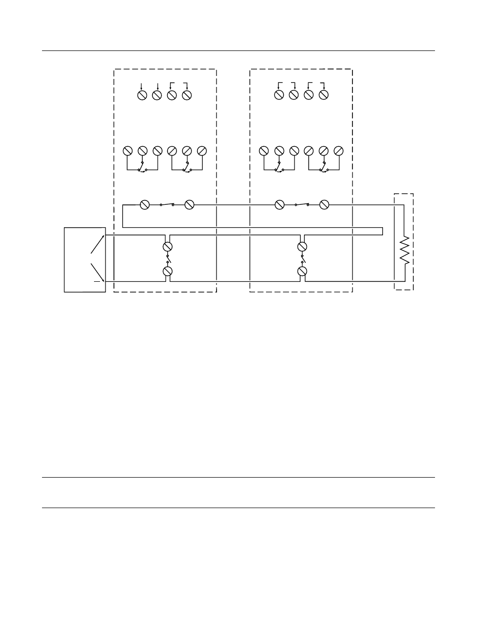
Wiring for 4-wire Duct Smoke Detector and Accessories
Important Notes on 2:1 Sensor-to-Power Capability
• 2:1 sensor-to-power capability is not available for all InnovairFlex models. The feature is only available on the D4120 4-wire conventional models.
• 2:1 sensor-to-power capability can be enabled using one D4120 and one D4S, or two D4S and one D4P120.
Important Interconnect Notes
• When using the interconnect feature, all interconnected units must be powered using the same independent supply.
• Polarity must be maintained throughout the interconnect wiring. Connect the INT+ terminal on unit 1 to the INT+ terminal on unit 2 and so on. Similarly,
connect the INT/AUX– terminal on unit 1 to the INT/AUX- terminal on unit 2 and so on.
• Up to 50 D4120 units, 50 D4P120 units, or 50 units of combination may be interconnected.
• Up to 10 DH100ACDC units may be interconnected. Please note that each of the 9 DH100ACDC units interconnected may be replaced by three D4P120
units. Therefore, when using the interconnect feature a single DH100ACDC can drive either 9 DH100ACDCs or 27 D4120 units.
* NOTE: Alarm can be reset only at the initiating device and not at the devices interconnected.
NOTE 1: 24V Power Inputs accept a non-polarized 24VDC or 24VAC 50-60Hz.
120VAC Power Inputs accept only 120VAC 50-60Hz. Connect power
source to appropriate terminals of each detector. See specifications
for additional power supply information.
NOTE 2: Auxiliary contacts shown in standby position. Contacts switch
during alarm as indicated by arrows. Auxiliary contacts are not to
be used for connection to the control panel. See specifications for
contact ratings.
NOTE 3: Supervisory contacts shown in standby position. Open contacts
indicate a trouble condition to the panel. See specifications for
contact ratings.
NOTE 4: Alarm Initiation contacts shown in standby position. Closed
contacts indicate an alarm condition to the panel. See specifications
for contact ratings.
*Please refer to the corresponding installation manual for accessory wiring diagrams.
24VAC/DC
9
10
AUXILIARY CONTACTS
FOR FAN SHUTDOWN, ETC. (NOTE 2)
16
6
17
8
18
7
N.O.
C.
N.C.
N.O.
C.
N.C.
16
6
17
8
18
7
N.O.
C.
N.C.
N.O.
C.
N.C.
SUPERVISORY CONTACTS
(NOTE 3)
24V
9
10
AUXILIARY CONTACTS
FOR FAN SHUTDOWN, ETC. (NOTE 2)
SUPERVISORY CONTACTS
(NOTE 3)
SUP C.
SUP N.O.
SUP N.O.
SUP C.
5
4
ALARM
INITIATION
CONTACTS
(NOTE 4)
5
4
ALARM
INITIATION
CONTACTS
(NOTE 4)
ALARM
INITIATION
LOOP
UL/FM LISTED
4-WIRE
CONTROL PANEL
+
120
VAC
120
VAC
OR
OR
AUX A
AUX B
AUX A
AUX B
ALARM C.
ALARM C.
ALARM N.O.
ALARM N.O.
14
14
3
3
FIRST DETECTOR IN THE LOOP
POWER INPUTS (NOTE 1)
POWER INPUTS (NOTE 1)
LAST DETECTOR IN THE LOOP
EOL RESISTOR
SPECIFIED BY
PANEL
MANUFACTURER