Greenheck Single 3-Sided Retaining Angle Supplement - Vertical Mount (473768) User Manual
Installation instruction supplement, Fsd series, Multi-blade dfd series
These instructions apply to 11/2 hour rated
combination fire smoke dampers and fire dampers
mounted in masonry, block, or metal or wood stud
walls. Specific requirements in these instructions are
mandatory. These instructions meet the requirements
of UL 555.
Installation shall comply with the requirements
of NFPA 90A (Standard for the Installation of Air
Conditioning and Ventilating Systems) and UL
Classification R13317.
Dampers up to a maximum size of 80 in. W x 50 in. H
(2032mm x 1270mm), 50 in. W x 80 in. H (1270mm x
2032mm), or 40 in. W x 100 in. H (1016mm x 2540mm)
may be installed as illustrated below.(Larger damper
assemblies require retaining angles on both sides of
the partition.)
• Retaining angles must be attached to the sleeve
and the partition.
• Retaining angles for dampers with a width
and height 48 in. (1219mm) or less must be a
minimum of 20 ga. (1mm). Retaining angles for
all dampers with a width or height greater than
48 in. (1219mm) must be a minimum of 16 gauge
(1.5mm). The leg of the retaining angle on the
damper sleeve shall be a minimum of 11/4 in.
(32mm). The leg of the retaining angle on the
wall shall be long enough to cover the annular
space and overlap the wall by at least 1 in.
(25mm).
For metal stud partitions only, the single-side
mounting angle may be directly attached to the
metal stud prior to the installation of the drywall.
• Retaining angles must be attached to the sleeve
using one of the methods shown below:
• tack or spot welds
• #10 sheet metal screws
• 1/4 in. (6mm) nuts and bolts
• Retaining angles must be attached to the
partition using one of the methods shown
below:
• Drywall screws of a length such that the
screw engages the steel stud/track by 1/2
in. (13mm) (steel framing).
INSTALLATION INSTRUCTION SUPPLEMENT
Refer to:
‘Installation Instructions for FSD-XXX, DFD-
XXX, SSFSD-XXX & CFSD-XXX Series Fire
& Combination Fire Smoke Dampers’ (Part
#461336)
Document number 473768
Single 3-Side Retaining Angle-Vertical Mount
Floor Installation
FSD Series
1
1
/
2
Hour Combination Fire Smoke
Dampers-Vertical Mount
MULTI-BLADE DFD Series
1
1
/
2
Hour Fire Dampers-Vertical Mount
“UL CLASSIFIED
(see complete marking on product)”
“UL CLASSIFIED to Canadian safety standards
(see complete marking on product)”
Standards UL 555 & 555S
Classifications Filed at UL under Listing #R13317
• Drywall screws of a length such that the
screw engages the wood stud by 13/4 in.
(44mm) (wood framing).
• Steel anchors or self tapping concrete
screws penetrating masonry or block 11/4
in. (31mm).
• On the top and sides of the damper a minimum
of two connections are required between the
retaining angles and the sleeve and between the
retaining angles and the partition. On dampers
with a maximum width of 48 in. (1219mm) and a
maximum height of 36 in. (914mm) the maximum
spacing between connections shall be 12 in.
(305mm). On dampers with a width greater
than 48 in. (1219mm) or a height greater than
36 in. (914mm) the maximum spacing between
connections shall be 6 in. (152mm).
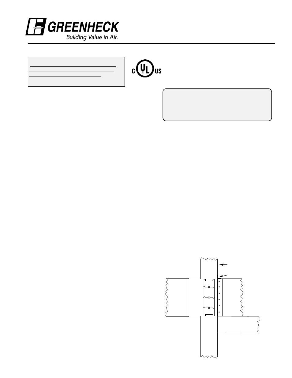
• A retaining angle is not required on the bottom
side of the damper. However, the damper shall
rest directly on the base of the wall opening. In
addition, the sleeve on the retaining angle side
of the barrier shall not be more than 1 in. (25mm)
above the floor.
Rated Wall
Ductwork
Floor
Retaining Angle
®