Fatpa direct drive series instructions – Greenheck MSxx04 & MSxx09 Series External (477252) User Manual
Page 2
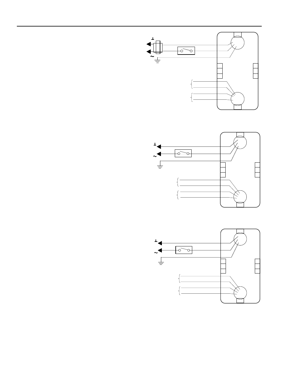
Figure 2: MS Series wiring illustration.
FATPA DIRECT DRIVE SERIES
INSTRUCTIONS
These installation instructions assume the damper is
already mounted in a duct or sleeve with the damper
shaft extending beyond the duct or sleeve 6 inches
(152mm).
1. Install the stand-off bracket
Dampers with a jackshaft
1a. Remove the 1/2 in. (13mm) ball bearing from the
standoff bracket. Mount the stand-off bracket (item
#7) with [4] 1/4-20 x 1/2 in. (M6 x 12mm) spinlock
bolts and nuts (item #4 and 5). Orient the stand-off
bracket (item #7) so the hole is centered on the
jackshaft (see Figure 1, With Jackshaft).
Dampers without a jackshaft (Shaft Extension)
1b. Mount the stand-off bracket (item #7) spanning
across the damper frame flanges. Fasten to the
damper frame with [4] 1/4-20 x 1/2 in. (M6 x 12mm)
spinlock bolts and nuts (item #4 and 5). Be sure not
to run the screws into the damper linkage, which is
between the flanges.
2. Mount actuator bracket
Fasten the actuator bracket (item #1) (See Figure
1) to the standoff bracket (item #7) using [4] 1/4-20 x
1/2 in. (M6 X 20mm) spinlock bolts and nuts (item #4
and 5). Use outer four holes of the actuator bracket
(item #2).
3. Fail Position
If fail position is closed, make sure damper
blades are fully close and ensure blade seals are
compressed prior to tightening the actuator clamp
to the damper extension pin or jackshaft.
4. Install the actuator
Install the actuator (item #6) over the damper drive
shaft and tight against the actuator bracket (item
#1). Install [1] #10-24 x .375 shoulder bolts (item #2)
through lugs on actuator and through the holes in
back of the actuator bracket (item #1). Secure with
[2] #10-24 nuts (Item #5) (See Figure 1).
5. Secure actuator (Item #6) to drive shaft by
tightening the set screws on actuator collar.
6. The wiring illustration identifies actuator electrical
requirements and connections (See Figure 2).
Wiring must comply with all applicable electrical
codes.
7. Apply power to the actuator. The damper blades
should fully open or close and return to the fail
position when power is disconnected.
M34624
24 VAC
BLACK
RED
GREEN
L1 ( )
L2 ( )
YELLOW
YELLOW
BLUE
7° AUXILIARY
SWITCH
85° AUXILIARY
SWITCH
BLUE
24 VAC wiring diagram
120 VAC wiring diagram
230 VAC wiring diagram
WHITE
BLACK
GREEN
L1 ( )
L2 ( )
YELLOW
YELLOW
BLUE
BLUE
7° AUXILIARY
SWITCH
85° AUXILIARY
SWITCH
120 VAC
M34625
M34626
BLUE
BROWN
GREEN
230 VAC
L1 ( )
L2 ( )
YELLOW
YELLOW
BLUE
BLUE
7° AUXILIARY
SWITCH
85° AUXILIARY
SWITCH
2