Greenheck Mounting Kit for Actuators used on Control Dampers (479869) User Manual
Instructions, Warning
DOCUMENT NUMBER 479869
MOUNTING KIT FOR ACTUATORS
Belimo and Honeywell models
Installation, Operation, and Maintenance Instructions
These instructions apply to the internal or external field replacement of mounting hardware for direct drive
actuators (Belimo and Honeywell [except MS7505 and MS8105 series] ) on Greenheck control dampers when
they are duct mounted or sleeved.
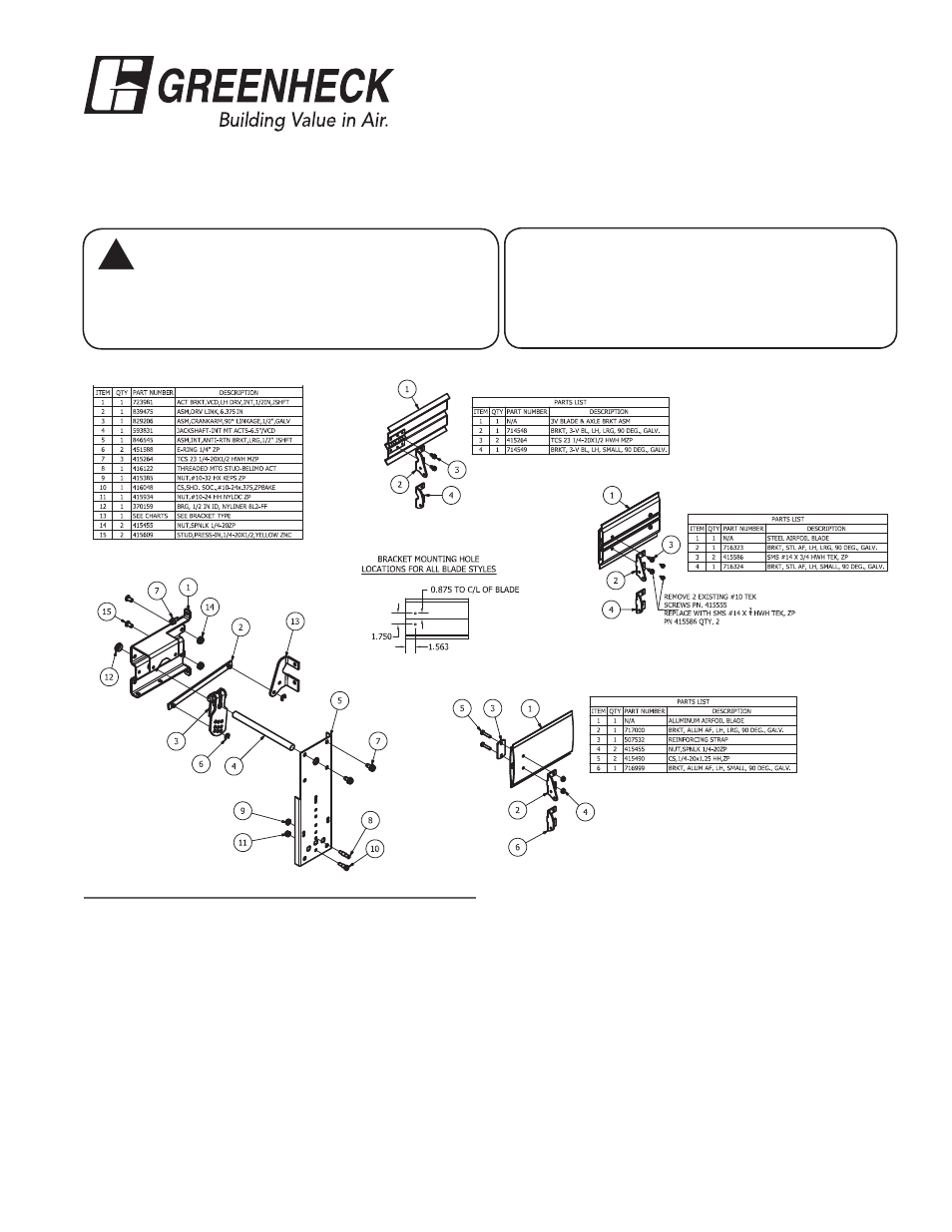
PART NO. 872700: INTERNAL MOUNT - 1/2 IN. PIN OR JACKSHAFT
3-V Blade
Steel Airfoil Blade
Aluminum Airfoil Blade
Instructions
1. Have damper in desired fail position.
2. Drill (2) 0.203 inch holes in the first blade (when one
or two blade damper) or third blade (more than a two
blade damper) at a location as shown above for the
blade type you have.
3. Attach blade drive lever (item #13) using two fasteners
(see list above based on blade type). Note: Shaft (item
#4) needs to be centered with the centerline of the
blade.
4. Fasten actuator bracket (item #1) to the left jamb of
damper frame using (1) thread cutting screw in top tab
of bracket (0.203 in. hole is required). Note bottom tab
does not get a fastener. Install (2) 1/4 -20 x 1/2 studs
(item #15) and nuts (item #14) through holes in damper
frame. Snap bearing (item #12) into internal actuator
bracket.
5. Slide 1/2 in. diameter shaft (item #4) slightly through
the anti-rotation bracket (item #5). Install crankarm
(item #3) and drive link (item #2) onto the 1/2 in.
diameter shaft (item #4) and install e-clip (item #6) to
lock drive link (item #2) on the crankarm (item #3).After
the crankarm is installed, slide 1/2 in. shaft through the
bearing (Item #12).
6. Install shoulder bolt (items #8 or 10) to the anti-rotation
bracket (item #5) using nut (item #9 or 11). Bolt
location will vary depending on the actuator model.
7. Slide the anti-rotation bracket (item #5) over the 1/2
in. shaft. Fasten to actuator bracket (item #1) using
thread cutting screws (item #7). Attach actuator to
Tools Required:
Wrenches: (1)
7
⁄
16
in., (1)
3
⁄
8
in., (1)
9
⁄
16
in.
(1) Ratchet with
3
⁄
8,
7
⁄
16, 9
⁄
16
in. deepwell socket
(1)
1
⁄
8
in. Allen wrench,
(1) Drill with
3
⁄
8
in. and 9/32 in. nut driver,
(1) .203 dia. drill bit
!
!
WARNING
Equipment Damage or Electrical Power Hazard.
Line voltage can cause death or serious injury
and short circuit equipment. Disconnect power
supply before installation.
®