Maintenance warning, Operation – Greenheck TCB/TCBRU/TCBRS (456557) User Manual
Page 3
PRE-START UP CHECKS
1. Check all fasteners for tightness.
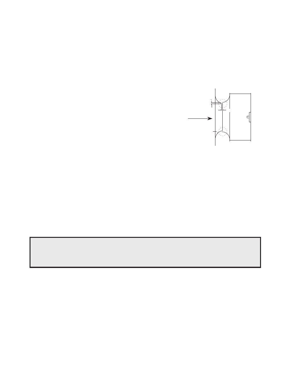
2. The wheel should be aligned as shown in Fig. 4. Although the wheel position is preset and the unit is test run at the
factory, movement may occur during shipment.
3. Wheel rotation should be in the same direction as the rotation decal affixed to the unit. For 3-phase installations, fan
rotation can be reversed by simply interchanging any two of the three electrical leads. For single phase installations,
follow the wiring diagram located on the motor.
4. Adjustable motor pulleys are preset at the factory for the specified fan RPM. Fan speed can be increased by closing or
decreased by opening the adjustable pulley. Two or three groove variable pitch pulleys must be adjusted an equal number
of turns open or closed.
Note: Any increase in fan speed represents a substantial increase in horsepower required from the
motor. Always check motor load amperage and compare to name plate rating when changing fan
speed.
ELECTRICAL CONNECTIONS
Before electrical connections are made, the supply voltage, phase and ampere capacity must be checked for compatibility
with the fan motor. In addition, the supply wiring must be properly fused and conform to local and national electrical codes.
The supply wires are then connected to an optional safety disconnect switch (if supplied) or wired directly to the motor.
MAINTENANCE
WARNING
DISCONNECT AND SECURE TO THE “OFF” POSITION ALL ELECTRICAL POWER TO THE
FAN PRIOR TO INSPECTION OR SERVICING. FAILURE TO COMPLY WITH THIS SAFETY
PRECAUTION COULD RESULT IN SERIOUS INJURY OR DEATH.
Once the fan has been put into operation, a periodic maintenance program should be set up to preserve the reliability and
performance of the fan. Items to be included in this program are:
• BEARINGS
• SET SCREWS
• BELTS
• MOTORS
• FASTENERS
• REMOVAL OF DUST/DIRT
BEARINGS
Bearings are the most critical moving part of the fan and should be inspected at periodic intervals. Locking collars and set
screws, in addition to fasteners attaching the bearing to the bearing plate, must be checked for tightness. In a clean
environment and temperature above 32
°F
and below 200
°F
, fan shaft bearings with grease fittings should be lubricated semi-
annually using a high quality lithium based grease. If unusual environmental conditions exist such as temperatures below 32
°F
and above 200
°F
, moisture or contaminants, more frequent lubrication is required.
With the unit running, add grease very slowly with a manual grease gun until a slight bead of grease forms at the seal. Be careful
not to unseat the seal by over lubricating or using excessive pressure. Bearings without grease fittings are lubricated for life.
OPERATION
Wheel
Inlet Cone
Radial Gap
Fig. 4
Overlap
Direction
of Airflow
The radial gap should be consistent at all locations between
the centrifugal wheel and the inlet cone. Centering may be
accomplished by loosening the inlet cone bolts and
repositioning the inlet cone.
To obtain the optimum performance, the centrifugal wheel
must overlap the inlet cone. Adjustments can be made by
loosening the set screws in the wheel and moving the wheel
to the desired position.