Typical installations, Operation and unit start-up, Electrical connections – Greenheck AX (464664) User Manual
Page 4: Pre-start-up checks
4
Axial Fan
Units with Flange Mounting
• Upblast, Downblast or Horizontal
Roof Upblast on a Roof Curb
Wall Mounted (Short Casing)
Units with Universal Mounting Brackets (Optional)
• Vertical, Ceiling Mount with Isolators,
Downblast or Upblast
• Horizontal, Floor or Ceiling Mount with Isolators
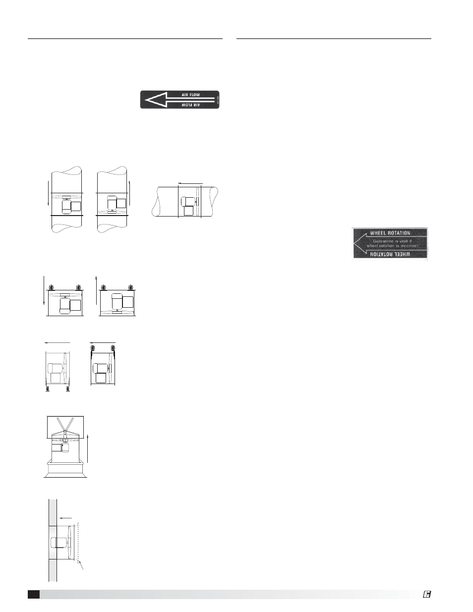
Typical Installations
The examples shown below are common installations
of the different housing options with and without
optional Universal Mounting Brackets. Before beginning
installations, reference the airflow direction as indicated
by the direction decal
attached to the fan. Note
that airflow for AX units
with straightening vanes is
opposite of the standard AX
long casing design.
Airflow
Direction Decal
Airflow
Airflow
Airflow
Airflow
Airflow
Airflow
Airflow
Airflow
Optional
Inlet Bell
Airflow
Operation and Unit Start-Up
Electrical Connections
Before electrical connections are made, the supply
voltage, phase and ampere capacity must be checked
for compatibility with the fan motor. In addition, the
supply wiring must be properly fused and conform to
local and national electrical codes.
The supply wires are then connected to an optional
safety disconnect switch, to the optional wiring pigtail,
or directly to the motor junction box.
Pre-Start-Up Checks
1. Check all fasteners for tightness. Fasteners may
come loose during transit or handling at the jobsite.
This includes motor bolts, mounting brackets, and
bushing bolts attaching the propeller to the motor
shaft.
2. Propeller rotation should be in the same direction
as the rotation decal affixed to the unit. For 3-phase
installations, fan rotation can be reversed by simply
interchanging any two
of the three electrical
leads. For single phase
installations, follow the
wiring diagram located on
the motor.
Propeller Rotation
Decal
®