Fatpa direct drive series instructions – Greenheck ML4XXX, ML8XXX series external (458403) User Manual
Page 2
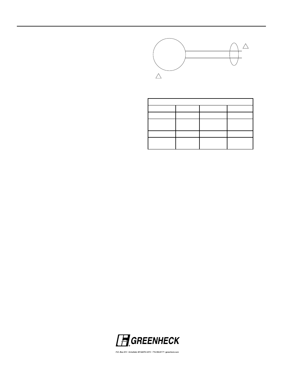
Black
White (120 Vac)
L
1
(Hot)
M
L
2
Red (24 Vac)
Power supply. Provide disconnect and means of overload protection.
1
1
Copyright ©2009 Greenheck Fan Corporation
458403 IOM - FATPA Rev 7 June 2009
Figure 3: FATPA Series wiring illustration.
Actuator Weight
5 lb (2.3 kg).
noise Rating
Driving Open: Maximum 65 dBA at 1m.
Holding: Maximum 20 dBA at 1m (no audible noise).
Temperature Ratings
Ambient: 0°F to 130°F (-18°C to 55°C)
Shipping and Storage: -40°F to 140°F (-40°C to 60°C)
Humidity Ratings
5% to 95% RH non-condensing.
Environmental Protection Ratings
NEMA 1
IP42
Approvals
Underwriters Laboratories Inc. UL 873 plenum rating,
and cUL: File #E4436: Guide #XAPX.
Direction of Spring Return
Counterclockwise (see Figure 1, see note)
MS4309, ML4302
MS8309, ML8302
Clockwise (see Figure 1, see note)
MS4209, ML4202
MS8209, ML8202
Actuator Timing (under Load)
Drive Open: 15 seconds.
Spring Close: 15 seconds.
FATPA DIREcT DRIvE SERIES
InSTRucTIonS
Power consumption
Model
Volts
Running
Holding
ML4XXX
120
18W
9W
MS4209
MS4309
120
23W
7W
ML8XXX
24
16W
8W
MS8209
MS8309
24
23W
7W
These installation instructions assume the damper is already
mounted in a duct or sleeve with the damper shaft extending
beyond the duct or sleeve 6 inches (152mm).
1. Install the stand-off bracket
Dampers with a jackshaft
1a. Jackshaft supplied is typically 1 in. (25 mm) diameter.
Mount the stand-off bracket (item #2) with [4] 1/4-20 x 1/2
in. (M6 x 12mm) self drilling screws (item #3). Orient the
stand-off bracket (item #2) so the hole is centered on the
jackshaft (See Figure 1).
Dampers without a jackshaft (Shaft Extension)
1b. Mount the stand-off bracket (item #2) spanning across
the damper frame flanges. Fasten to the damper frame
with [4] 1/4-20 x 1/2 in. (M6 x 12mm) self drilling screws
(item #3). Be sure not to run the screws into the damper
linkage, which is between the flanges.
2. Mount actuator bracket
Fasten the actuator bracket (item #6) (See Figure 1) to
the standoff bracket (item #2) using [4] 1/4-20 x 1/2 in. (M6 X
20mm) thread studs (item #4) and [4] 1/4-20 (M6) nuts (item
#5). Use outer four holes of the actuator bracket (item #6)
(See Figure 2).
3. Fail Position
If fail position is closed, make sure damper blades are
fully close and ensure blade seals are compressed prior to
tightening the actuator clamp to the damper extension pin
or jackshaft.
4. Install the actuator
Install the actuator (item #1) over the damper drive shaft
and tight against the actuator bracket (item #6). Install [2]
1/4-20 x 1/2 in. (M6 x 20mm) shoulder bolts (item #4) through
lugs on actuator and through the holes in back of the
actuator bracket (item #6). Secure with [2] 1/4-20 M6 nuts
(Item #5) (See Figure 1).
5. Secure actuator (Item #1) to drive shaft by tightening the
set screws on actuator collar to 50-55 in. lbs. (5.6 - 6.2
Nm).
6. The wiring illustration identifies actuator electrical
requirements and connections (See Figure 3). Wiring must
comply with all applicable electrical codes.
7. Apply power to the actuator. The damper blades should
fully open or close and return to the fail position when
power is disconnected.
IMPORTANT
For actuators with a product date code before 0527m
a power break of less than two seconds can cause the
actuator to spring-return 5 degrees or less and remain
in place until a power break of longer duration. For
actuators with a product date code of 0527 or after, a
power break of any duration will cause the actuator to
spring-return and be able to drive immediately when
power is reapplied.