Instructions fatpa direct drive series – Greenheck ML4XXX, ML8XXX series (459011) User Manual
Page 2
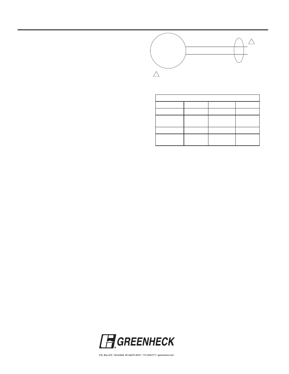
Black
White (120 Vac)
L
1
(Hot)
M
L
2
Red (24 Vac)
Power supply. Provide disconnect and means of overload protection.
1
1
Copyright © 2013 Greenheck Fan Corporation
459011 Internal FATPA Rev. 9 April 2013
Figure 2: FATPA series wiring illustration.
Actuator Weight
5 lb. (2.3 kg).
Noise Rating
Driving Open: Maximum 65 dBA at 1m.
Holding: Maximum 20 dBA at 1m (no audible noise).
Temperature Ratings
Ambient: 0°F to 130°F (-18°C to 55°C)
Shipping and Storage: -40°F to 140°F (-40°C to 60°C)
Humidity Ratings
5% to 95% RH non-condensing.
Environmental Protection Ratings
NEMA 1
IP42
Approvals
Underwriters Laboratories Inc. UL 873 plenum rating,
and cUL: File #E4436: Guide #XAPX.
Direction of Spring Return
Counterclockwise (see Figure 1, Note 3)
MS4309,
ML4302
MS8309,
ML8302
Clockwise (see Figure 1, Note 3)
MS4209,
ML4202
MS8209,
ML8202
Actuator Timing (Under Load)
Drive Open: 15 seconds.
Spring Close: 15 seconds.
INSTRUCTIONS
FATPA DIRECT DRIVE SERIES
Power Consumption
Model
Volts
Running
Holding
ML4XXX
120
18W
9W
MS4209
MS4309
120
23W
7W
ML8XXX
24
16W
8W
MS8209
MS8309
24
23W
7W
These installation instructions assume a damper is already
mounted in a duct or sleeve. Have damper blades in the fail
position.
1. Drill [2] .203 inch holes in the third blade from bottom,
at location shown in detail "A".
2. Attach blade drive lever to blade using [2] 1/4 in. - 20 x
1/2 in. thread cutting screws, self drilling screws or 1/4
-20 x 11/4 in. bolts.
3. Fasten actuator bracket (item 1) to the left jamb of
damper frame using [2] thread cutting screws. Note:
the 0.563 in. hole in the bracket (item 1) that the 6 1/2
in. jackshaft (item 5) goes through must be centered
with the centerline of the blade. Snap bearing (item 9)
into internal actuator bracket (item 1).
4. Snap bearing (item 9) into anti-rotation bracket (item 6)
and attach the anti-rotation bracket assembly (item 6)
to the internal mount bracket (item #1) using [2] thread
cutting screws (item 8).
5. Slide
1/2 in. diameter rod (item 5) slightly through the
anti rotation bracket (item 6). Install crankarm (item 3)
and drive link (item 2) onto the 1/2 in. diameter rod (item
5) and install retaining clip (item 10) to lock drive link
onto the crankarm.
6. Install 10-24 x .375 shoulder bolt (item 11) to the anti
rotation bracket (item #6) using #10 Nylock nut (item
12).
7. Attach actuator (item #7) to anti-rotation bracket
assembly (item 6). Tighten the actuator onto the shaft.
8. Connect drive link to blade drive lever using e-clip.
With blades closed and the actuator in its fail position,
position the blades in their fail position and tighten the
crankarm to the 1/2 in. shaft.
9. Connect all electrical leads to the actuator. Apply
power to the actuator. The damper blades should
power position and return to the fail position when
power is disconnected.
IMPORTANT
For actuators with a product date code before 0527 a
power break of less than two seconds can cause the
actuator to spring-return 5 degrees or less and remain
in place until a power break of longer duration. For
actuators with a product date code of 0527 or after, a
power break of any duration will cause the actuator to
spring-return and be able to drive immediately when
power is reapplied.